

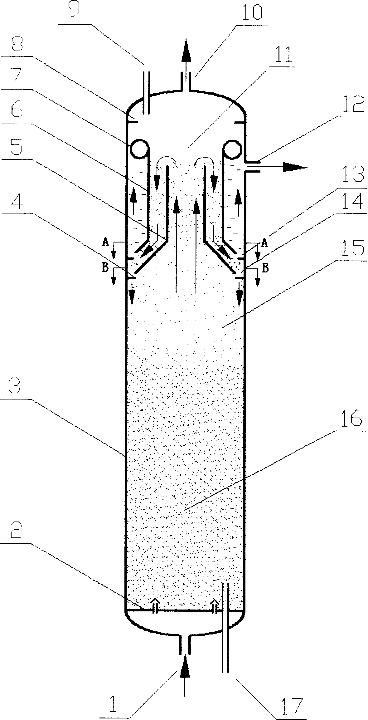
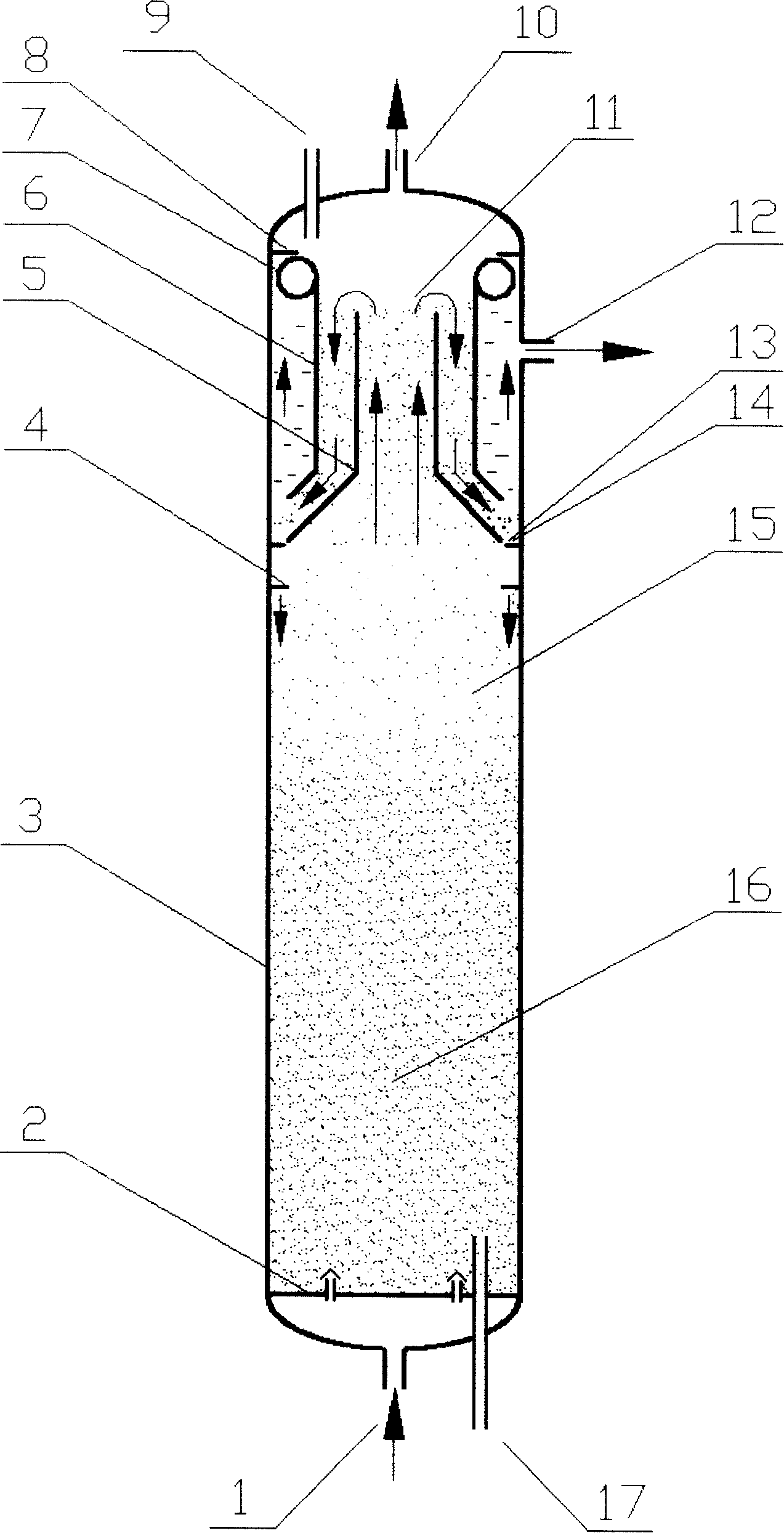
Three-phase fluidized bed reactor
A fluidized bed reactor and reactor shell technology, applied in chemical instruments and methods, chemical/physical processes, etc., can solve the problems of inability to guarantee operation, reduce product quality, catalyst loss, etc., and achieve long-term stable operation. Avoid a large number of carry out and ensure the effect of efficient separation
- Summary
- Abstract
- Description
- Claims
- Application Information
AI Technical Summary
Problems solved by technology
Method used
Image

Examples
Embodiment -1
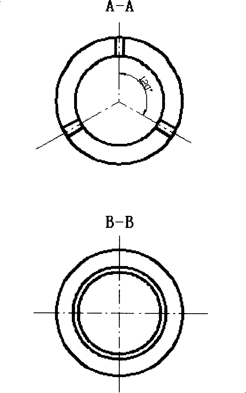
[0037] According to the selection of the three-phase separator size of the present invention, a three-phase separator fluidized bed medium-sized reactor cold mold test has been carried out, and the size of the medium-sized cold mold device is: the inner diameter of the reactor shell=160mm, the diameter of the reactor shell Height = 3000mm, shell effective volume 60L, separator height = 380mm, diameter of the cylindrical part of the central tube of the separator = 92mm, bottom diameter of the tapered opening at the lower part of the inner cylinder = 144mm, height of the lower cone part of the inner cylinder = 41mm, outer The diameter of the cylindrical part of the cylinder = 128mm, the diameter of the bottom of the opening of the conical part = 138mm, the height of the conical part = 64mm, the section of the buoy is circular, the diameter = 100mm, its lower edge is connected with the top of the outer cylinder of the separator, and the upper part of the buoy The height difference...
Embodiment -2
[0040] Based on the cold model test, a hydrodemetallization test of atmospheric residue oil in sand was carried out on a 60L medium-sized device. Wherein the size of the reactor is the same as in Example 1, and the test conditions and results are shown in Table 2.
Embodiment -3
[0042] Based on the cold model test, a hydrodemetallization test of atmospheric residue oil in sand was carried out on a 60L medium-sized device. Wherein the size of the reactor is the same as in Example 1. After 1200 hours, it was found that the amount of catalyst carry-over increased rapidly, so the three-phase separator discharge port was decoked, and the amount of catalyst carry-over returned to the normal range after decoking. The test conditions and results are shown in Table 3.
[0043] Table 1 The relationship between the oil intake, intake air volume and catalyst carryover volume of the 60L cold mold device
[0044]
[0045] Note: The intake volumes of 6 and 7 are changed in a short period of time, which is used to examine the strain capacity of the three-phase separator.
PUM
| Property | Measurement | Unit |
|---|---|---|
| Angle | aaaaa | aaaaa |
Abstract
Description
Claims
Application Information