
Mechanical photo switch

An optical switch and mechanical technology, applied in the field of optical path switching components, can solve the problems of inaccurate alignment, difficult alignment accuracy, loss of alignment accuracy, etc., to achieve easy control and maintenance, improve assembly pass rate, and easy alignment The effect of precision

Inactive Publication Date: 2008-05-07
范光照
View PDF2 Cites 2 Cited by
  • Summary
  • Abstract
  • Description
  • Claims
  • Application Information

AI Technical Summary

Problems solved by technology

The disadvantage is that the optical fiber on the switching device is subjected to pre-pressure and groove reaction force during alignment, and the cantilever part of the optical fiber is bent and deformed, so that the alignment relationship of the two optical fibers is a curve to a straight line when the two optical fibers are directly aligned.
If the optical fiber end deformed into a curve is placed in a certain switching position for a long time, the optical fiber end will not be able to return from the curved shape to the original straight line shape, so when switching to another position, it will not be able to accurately align, and it will continue for a long time After switching, the original alignment accuracy will be lost
This design has disadvantages such as difficult assembly and difficult control and maintenance of alignment accuracy.

Method used


Image

  • Mechanical photo switch
  • Mechanical photo switch
  • Mechanical photo switch

Examples


Embodiment Construction

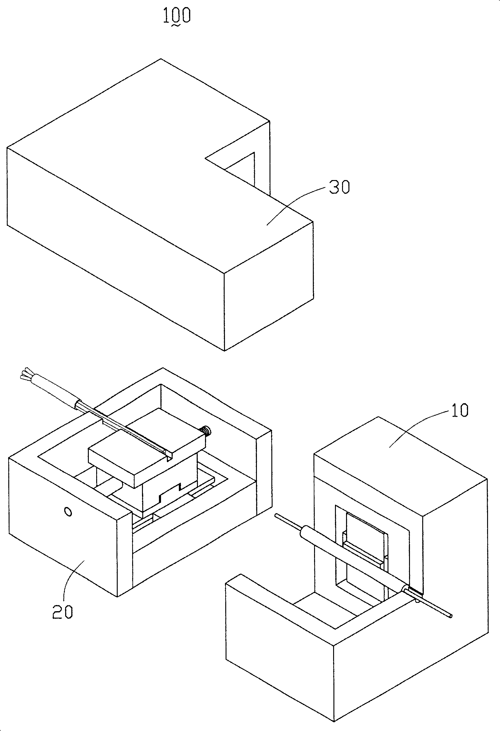
[0043] figure 1 It is a three-dimensional exploded view of the mechanical optical switch of the present invention. The mechanical optical switch 100 includes a first optical fiber module 10, a second optical fiber module 20 and an upper cover 30, wherein the first optical fiber module 10 is an input optical fiber module , the second fiber optic module 20 is an output fiber optic module.

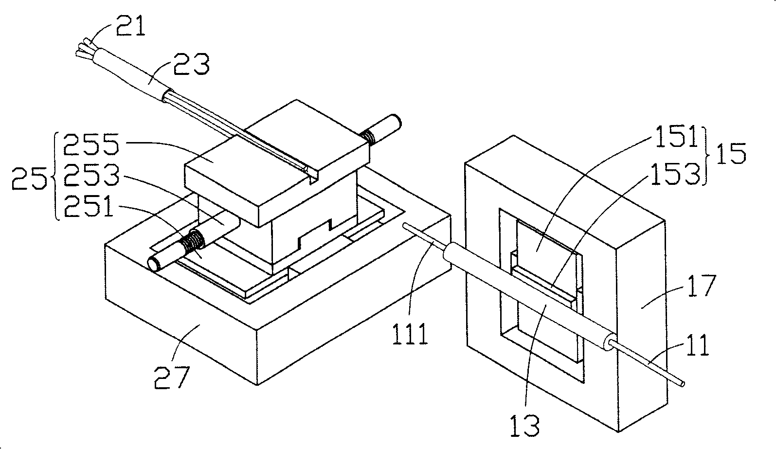
[0044] Please also refer to figure 2 , the first optical fiber module 10 includes a first optical fiber 11 , a ferrule 13 covering the first optical fiber 11 , an optical fiber switching device 15 and a base 17 . Wherein, a relay (not shown) is built in the base 17 , the fiber switching device 15 is accommodated in the base 17 , and the bushing 13 is fixedly installed on the fiber switching device 15 . The fiber switching device 15 includes a swing element 151 and a sleeve fixing element 153, which can drive the sleeve 13 and the first optical fiber 11 to move vertically, and the first opt...


PUM


Abstract

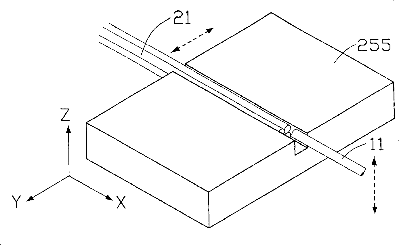
The invention discloses a mechanical light switch, comprising a first optical fiber module and a second optical fiber module arranged in the corresponding position of the first optical fiber module, wherein the first optical fiber module comprises a first optical fiber and a first optical fiber switching device, the second optical fiber module comprises at least two second optical fibers and a second optical fiber switching device. The tip of the first optical fiber switching device which controls the first optical fiber is shifted in horizontal or vertical direction, and the tip of the second optical fiber switching device which controls the second optical fiber is shifted in the vertical direction of the moving direction of the tip of the first optical fiber to enable the first optical fiber to be on the contraposition of the second optical fiber.

Description

technical field [0001] The present invention relates to an optical path switching element used in an optical fiber communication system, in particular to an optical switch that utilizes mechanical switching and is directly aligned with bare optical fiber ends (fiber to fiber). The optical switch of the present invention passes through the The design can increase the pass rate of the optical switch and at the same time improve the accuracy of the optical fiber alignment. Background technique [0002] The optical switch is one of the important components of the all-optical network, which can be used for direct, interleaved or multi-party transmission of optical signals in the optical fiber network system. Optical switches developed in the past use photoelectric conversion to first convert the input optical signal into an electrical signal, then switch the signal path, and finally convert the electrical signal into an optical signal and output it through a specific optical fibe...

Claims


Application Information

Patent Timeline
IPC IPC(8): G02B6/35
Inventor 范光照钟添东杨燿州林武郎
Owner 范光照
Learn More