Magnetron sputtering source, sputter coating system and method for coating a substrate

A magnetron sputtering and coating equipment technology, applied in sputtering coating, coating, discharge tube and other directions, can solve problems such as power density limitation and temperature reduction, and achieve the effect of reducing cost and shortening coating equipment

Inactive Publication Date: 2008-05-21
APPLIED MATERIALS INC
View PDF0 Cites 8 Cited by
  • Summary
  • Abstract
  • Description
  • Claims
  • Application Information

AI Technical Summary

Problems solved by technology

[0011] However, even cooling devices can only reduce the temperature of the uppermost atomic layer of the target to a limited extent
For example, in ITO sputtering, the maximum possible power density is limited by greater than about 3W / cm 2 The power density of the arc occurring under the limitation of this factor

Method used


Image

  • Magnetron sputtering source, sputter coating system and method for coating a substrate
  • Magnetron sputtering source, sputter coating system and method for coating a substrate
  • Magnetron sputtering source, sputter coating system and method for coating a substrate

Examples


Embodiment Construction

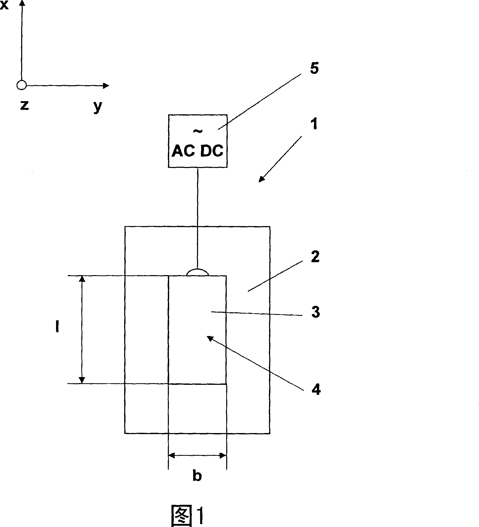
[0081] FIG. 1 shows a coating device 1 according to the invention in a sectional view. In the coating chamber 2 , an oblong cathode 3 with a length of 1 and a width of b is arranged, and a target 4 is installed on the cathode 3 . In this view, the cathode 3 is located below the target 4 within the page. However, within the scope of the invention, the cathode 3 and the target 4 can also be formed as an integral part, ie the cathode 3 can be formed from the target material 4 itself.

[0082] The cathode 3 is connected to a power source 5 by a connecting cable. Electrical energy can be coupled into the coating system 1 in the form of direct current, alternating current, unipolar pulsed current, bipolar pulsed current or RF (radio frequency) voltage.

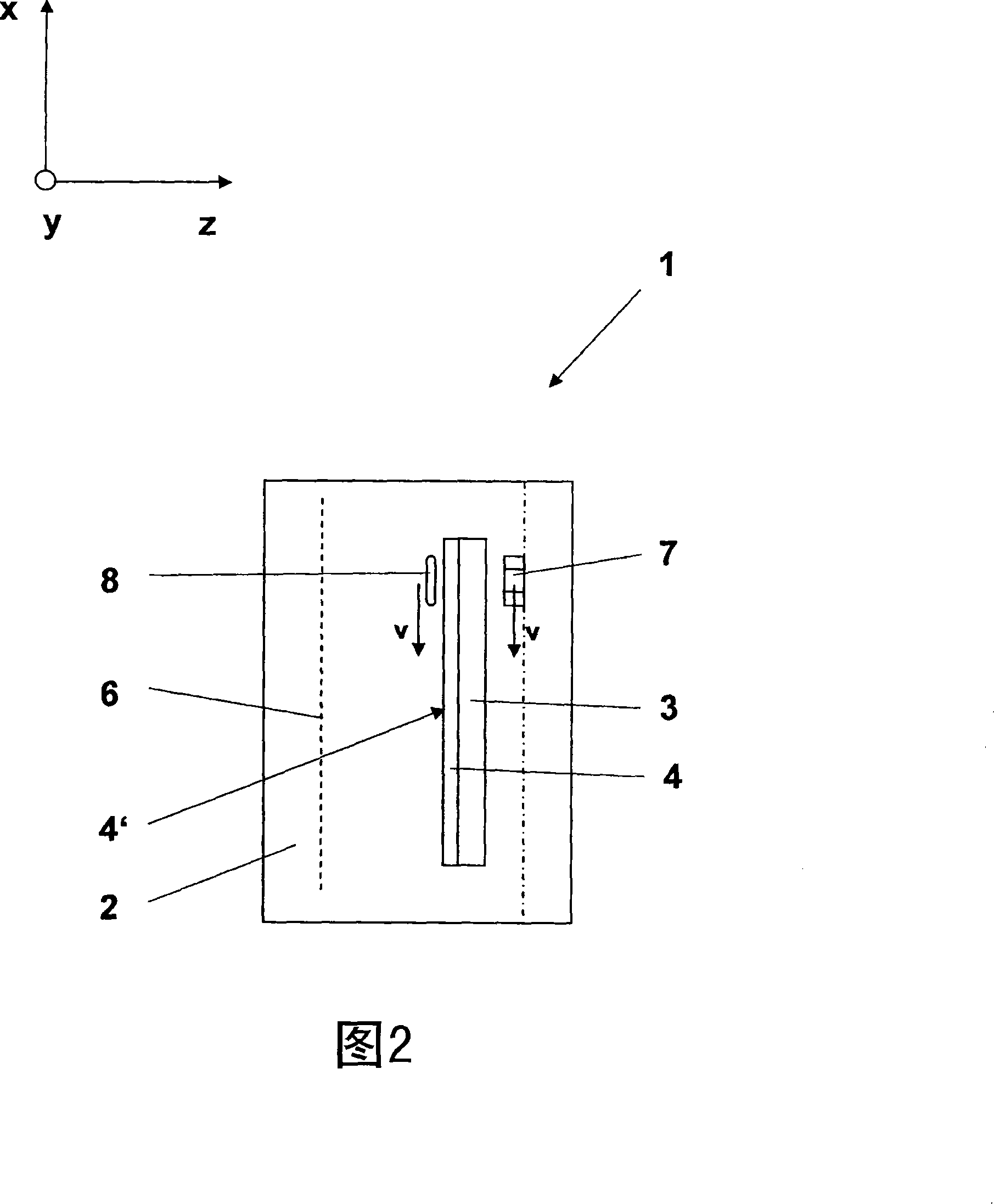
[0083] FIG. 2 shows a side view of the coating device 1 as indicated by the coordinate system in its upper left corner. In the coating chamber 2 delimited by walls, a cathode 3 and a target 4 mounted to the cathode 3 are arranged...


PUM


Abstract

The magnetron sputtering source for a coating unit (1), comprises a cathode (3), a target (4) assigned to the cathode or integrated into the cathode, means for producing a coating plasma, and a magnet arrangement (7) for producing a magnetic field for the influence of the coating plasma in such a way that a plasma channel (8) is produced over a part of the surface of the target, which provides coating- and / or treatment material. The magnet arrangement and the surface of the target are movably arranged relatively to each other by a drive. which is formed for the reduction of the thermal load of the target surface and an exposure time of the plasma on the surface area.

Description

technical field [0001] The invention relates to a magnetron sputtering source for a coating plant, comprising at least one cathode and at least one target, means for generating a coating plasma, at least one magnet part, said The target is arranged on the cathode or is integrated in the cathode and provides coating material and / or treatment material for coating and / or treatment; the at least one magnet part is used to generate coating-affecting plasma in the following manner The magnetic field of the body in such a way that at least one plasma channel is generated above the local surface of the target; the magnet part and the target are arranged such that they are preferably movable relative to each other by at least one drive. In addition, the present invention also contemplates a sputter coating device comprising at least one treatment or coating chamber and also a magnetron sputtering source. The invention also relates to a treatment method, in particular for coating a sub...

Claims


Application Information

Patent Timeline
Patent Type & Authority Applications(China)
IPC IPC(8): C23C14/35C23C14/54
CPCC23C14/3407H01J37/3408H01J37/3423C23C14/35H01J37/3455C23C14/3485
Inventor 乔格·克尔帕尔-汉斯
Owner APPLIED MATERIALS INC
Why Eureka
Try Eureka