
Tire road roller energy-saving control system

An energy-saving control system and a technology for tire rollers, applied in the field of tire rollers, can solve the problems of high mechanical loss of the power system, reduced total efficiency of the hydraulic system, reduced hydraulic pump displacement, etc. The effect of stable speed

Inactive Publication Date: 2008-05-21
SANY HEAVY IND CO LTD (CN)
View PDF0 Cites 17 Cited by
  • Summary
  • Abstract
  • Description
  • Claims
  • Application Information

AI Technical Summary

Problems solved by technology

In the design, the engine is configured with the maximum load, but in actual use, the working quality of the whole machine is different, the air pressure of the tire is different, the strength of the asphalt pavement increases during the rolling process, and the rolling resistance of the pneumatic tire decreases. The load is far lower than the design load value. Under low load conditions, the engine works at the rated speed, which will cause high mechanical loss of the power system. At the same time, the displacement of the hydraulic pump will be reduced, and the total efficiency of the hydraulic system will be reduced, resulting in fuel waste.

Method used


Image

  • Tire road roller energy-saving control system
  • Tire road roller energy-saving control system
  • Tire road roller energy-saving control system

Examples


Embodiment Construction

[0022] The present invention will be described in further detail below in conjunction with the accompanying drawings and specific embodiments.

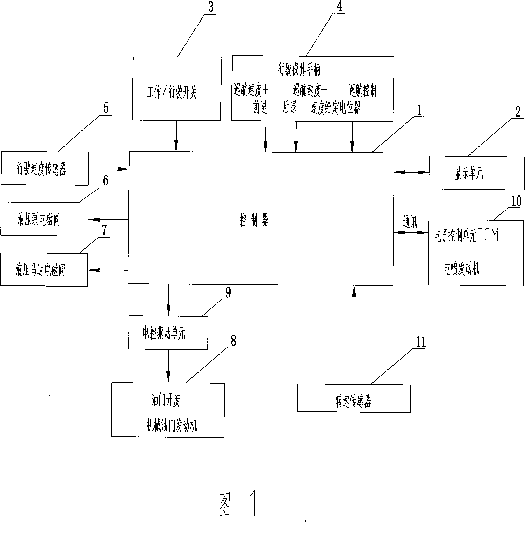
[0023] As shown in Figure 1, the tire roller energy-saving control system of the present invention includes a controller 1, a display unit 2, a travel speed sensor 5, an engine speed sensor 11 and a work / travel switch 3 for speed setting. The driving speed sensor 5 for detecting the speed signal of the tire roller and the engine speed sensor 11 for detecting the engine speed signal are connected to the input end of the controller 1, and the output end of the controller 1 is connected to the hydraulic pump electromagnetic valve 6 and the hydraulic motor of the tire roller. The solenoid valve 7 is connected to the display unit 2, the work / travel switch 3 is connected to the input end of the controller 1, and the controller 1 adjusts the displacement of the hydraulic pump according to the actual working condition load and on the premise t...


PUM


Abstract

An energy-saving control system of a tire road roller comprises a controller, a display unit, a driving speed sensor, an engine rotation speed sensor, and a working / driving switch. The driving speed sensor used to detect a speed signal of the tire road roller, and the engine rotation speed sensor used to detect a engine rotation speed signal are connected with the input end of the controller, while the output end of the controller is connected with a solenoid valve of a hydraulic pump, a solenoid valve of a hydraulic motor, and the display unit. The working / driving switch is connected with the input end of the controller. The controller adjusts the hydraulic pump displacement based on the actual working load and under the premise that that the hydraulic pump displacement is as large as possible, so when the actual speed of the tire road roller is equal to the set speed, the controller adjusts the engine rotation speed automatically. Thus, the hydraulic system and the mechanical transmission system work in a high-efficiency area, to reduce the fuel consumption. The control system is provided with the simple structure and the high automation degree, and capable of adjusting the engine speed automatically in the real time way, promotes the working efficiency of the whole tire roller, and is energy-saving and environment-protecting.

Description

technical field [0001] The invention mainly relates to the field of tire rollers in construction machinery, in particular to an energy-saving control system for tire rollers. Background technique [0002] As a self-propelled engineering vehicle, the tire roller is equipped with a diesel engine as a power device, which directly drives a hydraulic pump. The hydraulic oil is delivered to the hydraulic motor through the hydraulic pump, and then the hydraulic motor drives the traveling mechanism. By changing the displacement and direction of the hydraulic pump, the driving speed and direction of the tire roller can be changed. By changing the displacement of the hydraulic motor, the tire roller can have two speeds to meet the requirements of different working conditions of driving and compaction. In the working gear, the tire roller is guaranteed to carry out the compaction operation at a constant compaction speed, and in the driving gear, the tire roller can be driven at the fas...

Claims


Application Information

Patent Timeline
Patent Type & Authority Applications(China)
IPC IPC(8): E01C19/23
Inventor 邓连喜唐楚舒周巍
Owner SANY HEAVY IND CO LTD (CN)
Learn More