Deposition system and processing system

A processing system and deposition technology, applied in the fields of deposition systems and processing systems, can solve problems such as waste of sputtering materials, and achieve the effects of reducing chemical raw materials, improving utilization, and reducing target costs

Inactive Publication Date: 2008-05-28
ASCENTOOL
View PDF0 Cites 3 Cited by
  • Summary
  • Abstract
  • Description
  • Claims
  • Application Information

AI Technical Summary

Problems solved by technology

Another disadvantage of the deposition system 200 is

Method used


Image

  • Deposition system and processing system
  • Deposition system and processing system
  • Deposition system and processing system

Examples


Embodiment Construction

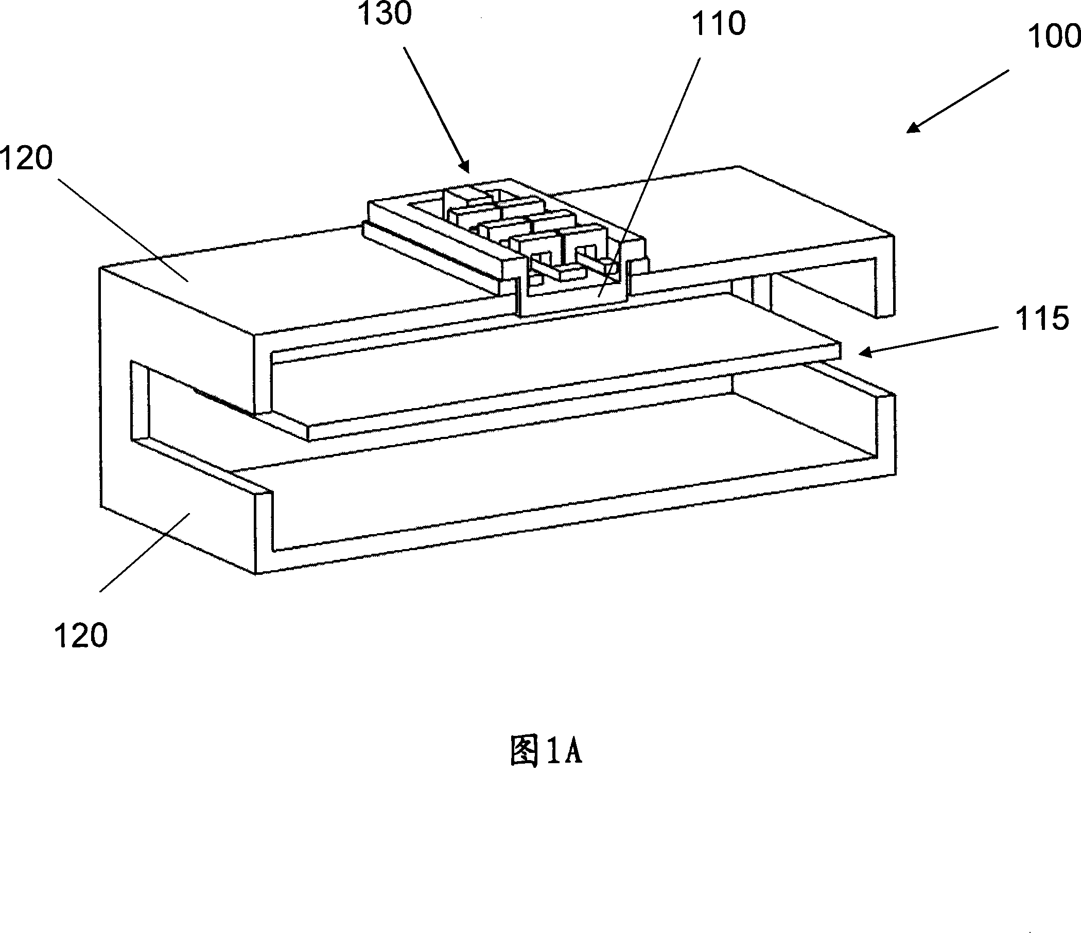
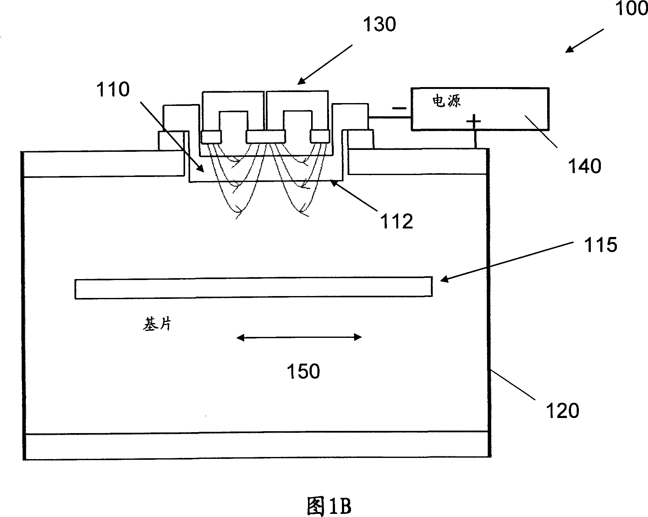
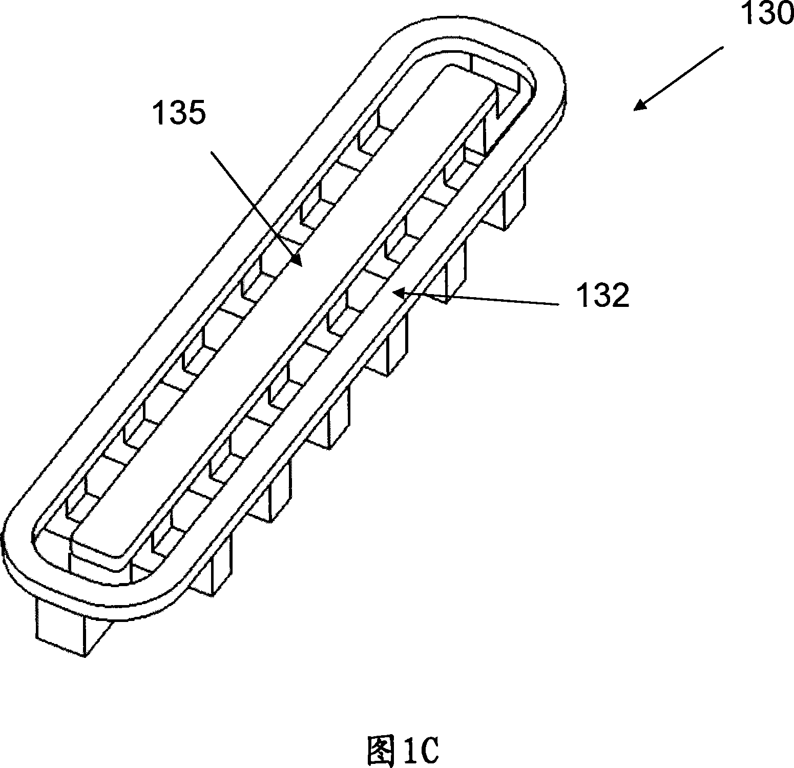
[0051] Referring to FIGS. 3A-3E , a processing system 300 includes a chamber 320 that may be sealed to form a vacuum environment in a space 350 . Processing system 300 may include a sputter deposition system or other types of processing stations as described below. Cavity 320 may include one or more inner cavity walls 321 a - 321 c , one or more outer cavity walls 325 a - 325 c , and end cavity walls 323 and 324 . The inner cavity walls 321a-321c and the outer cavity walls 325a-325c may form one or more pairs of opposing cavity walls.

[0052] A plurality of substrates 315a-315c may be disposed on outer cavity walls 325a-325c, respectively. A plurality of targets 310a-310c may be held on inner cavity walls 321a-321c, respectively. Each target 310 a , 310 b or 310 c includes a sputtering surface 312 facing the space 350 . Each substrate 315a, 315b or 315c includes a deposition surface 317 facing the space 350 and opposite the sputtering surface 312 on the corresponding targe...


PUM


Abstract

A deposition system includes a chamber, a plurality of targets in a center region in the chamber and a plurality of substrates in the chamber. The targets are sequentially positioned when viewed in a first direction. At least one of the targets includes a sputtering surface facing outward. The substrates are sequentially positioned when viewed in the first direction. At least one of the substrates includes a deposition surface configured to receive material sputtered off the sputtering surface.

Description

technical field [0001] The present application relates to apparatus for depositing material onto a substrate. The invention also relates to an apparatus for processing substrates. Background technique [0002] Material deposition is widely used in window glass coating, flat panel display manufacturing, coating on flexible films such as web (web), hard disk coating, industrial surface coating, semiconductor wafer processing, photovoltaic panels, and other in the field. Material deposition can be deposited on the substrate in the form of sputtered targets or evaporated material. A desired feature for material deposition is to maximize the utilization of target material and minimize waste of material. Another desirable feature for material deposition is to obtain a uniform deposition on the substrate. [0003] There are different designs for large substrates in conventional deposition systems. But these designs all have different drawbacks. In a first example, referring t...

Claims


Application Information

Patent Timeline
IPC IPC(8): C23C14/35C23C14/54C23C14/56C23C28/00
CPCH01J37/3423H01J37/3405H01J37/3408C23C14/352
Inventor 郭信生王开安
Owner ASCENTOOL
Why Eureka
Try Eureka