Hardware simulation systems and methods for vision inspection systems

a technology of vision inspection and simulation system, applied in the direction of electrical programme control, program control, instruments, etc., can solve the problems of insufficient off-line programming software tools for any machine that includes a machine vision system, inconvenient operation of modern image-based inspection and/or motion system, and inability to account for problems experienced, so as to improve operator training and reduce system downtime.

Inactive Publication Date: 2006-08-15
MITUTOYO CORP
View PDF21 Cites 23 Cited by
  • Summary
  • Abstract
  • Description
  • Claims
  • Application Information

AI Technical Summary

Benefits of technology

[0009]The synthetic images generated by the systems and methods of this invention may be used in place of the video captured by a camera in a hardware-based vision system. The systems and methods of this invention allow designers to readily develop an off-line version of an inspection system by replacing hardware-based software subsystems with subsystems that communicate with virtual components of a vision simulation engine. Operators are able to modify parameters in the virtual inspection system and immediately see the results as a change in the synthesized image. Because the inspection system simulation systems and methods of this invention are usable with existing vision inspection system user interfaces, a user may gain familiarity with the user interface prior to interacting with an actual physical vision inspection system.
[0010]The inspection system simulation systems and methods of this invention reduce system downtime due to creating new inspection part programs. The systems and methods of this invention are also able to improve operator training and to provide improved tools for off-site sales and marketing of vision inspection systems.

Problems solved by technology

However, these off-line programming software tools do not account for problems experienced when forming optical images through physical lens systems because such concerns are not present in traditional, non-image-based coordinate measurement machines or robots.
Therefore, these known off-line programming software tools are inadequate for any machine that includes a machine vision system and totally unsuitable for modern image-based inspection and / or motion systems.

Method used


Image

  • Hardware simulation systems and methods for vision inspection systems
  • Hardware simulation systems and methods for vision inspection systems
  • Hardware simulation systems and methods for vision inspection systems

Examples


Embodiment Construction

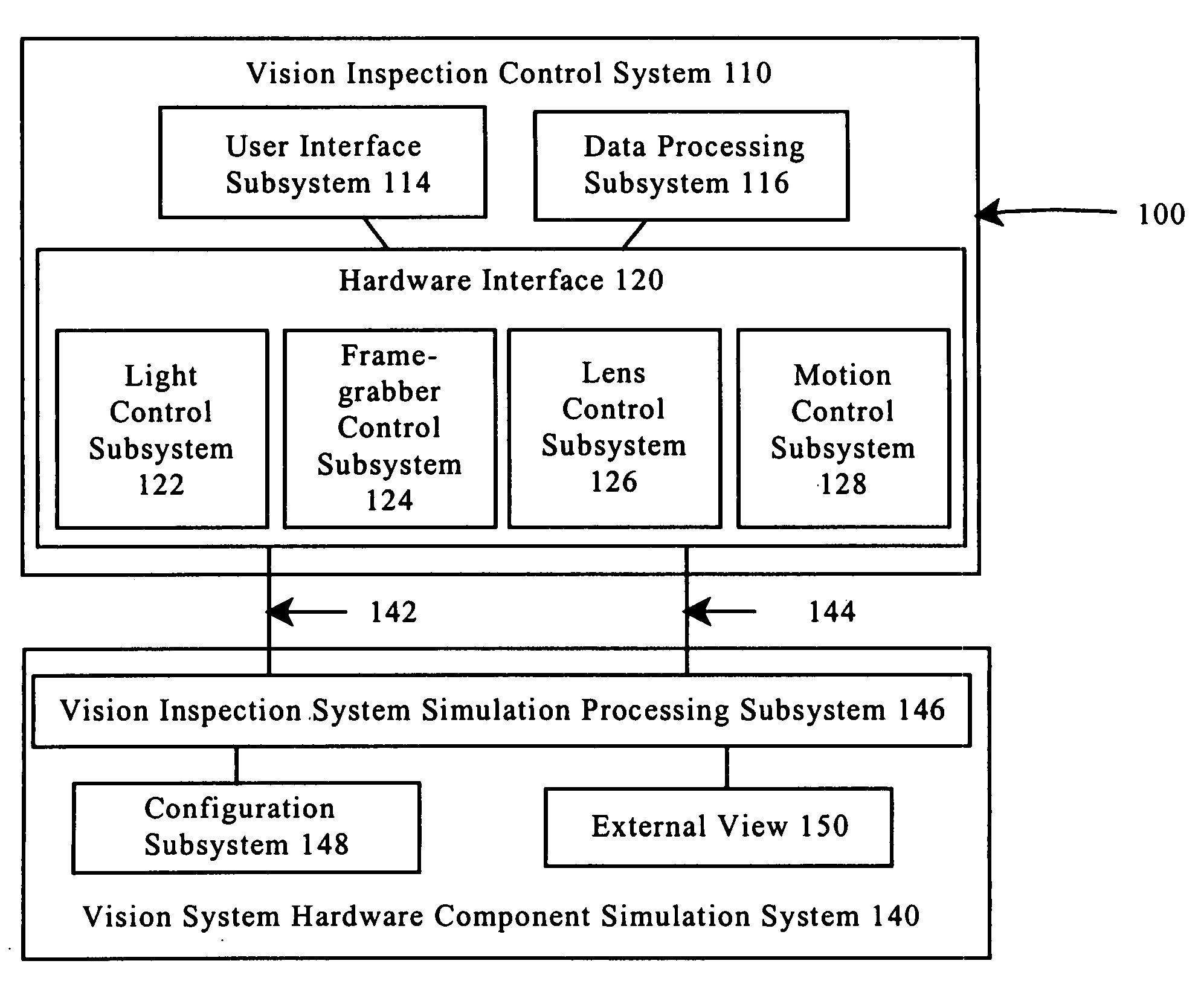
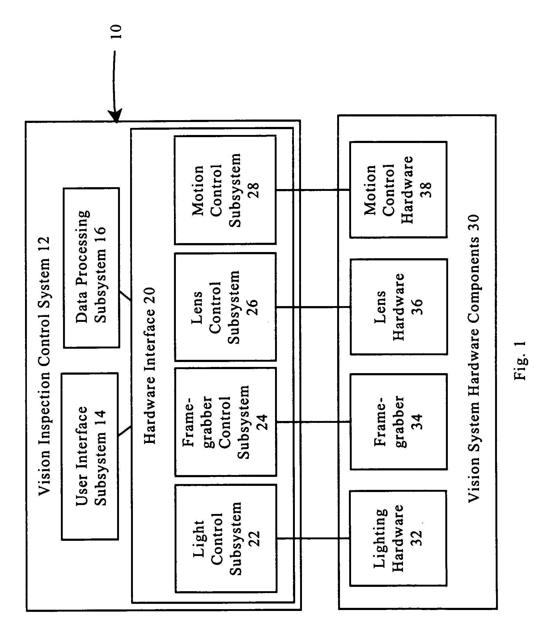
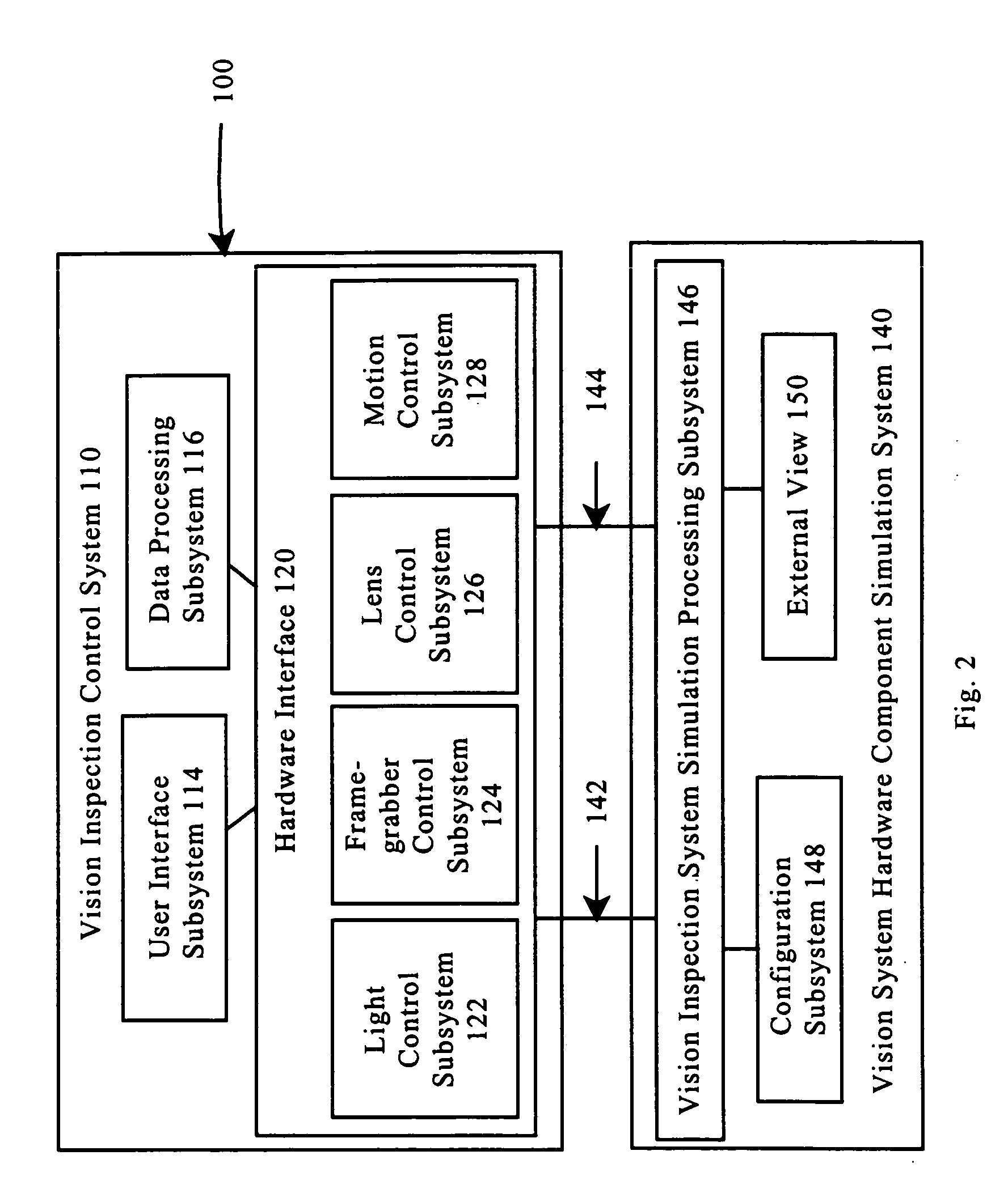
[0017]FIG. 1 is a block diagram of one exemplary embodiment of a physical vision inspection system 10. The vision inspection system 10 includes a vision inspection control system 12. The vision inspection control system 12 includes a user interface subsystem 14, a data processing subsystem 16 and a hardware interface 20. The hardware interface 20 includes a light control subsystem 22, a framegrabber subsystem 24, a lens control subsystem 26 and a motion control subsystem 28. The hardware interface 20 communicates with the vision system hardware components 30. In particular, the vision system hardware components 30 includes lighting hardware 32, framegrabber 34, lens hardware 36 and motion control hardware 38. The framegrabber 34 may include an internal or external framegrabber mechanism to produce still or real-time digital representations of a scene viewed by a monochrome or color camera. The camera and the framegrabber 34 combination described herein is intended to include both an...


PUM


Abstract

The systems and methods of this invention provide simulated images to vision inspection systems. The simulated images emulate the vision of a vision inspection system. Graphical models of objects in a virtual world and lens effects models are used to provide the simulated images.

Description

BACKGROUND OF THE INVENTION[0001]1. Field of Invention[0002]This invention is directed to methods and systems that simulate images produced by a vision system. More particularly, this invention is directed to methods and systems that generate a synthetic image that accurately approximates an image produced by an automated vision inspection system.[0003]2. Description of Related Art[0004]A wide variety of non-contact computer-vision-based systems exist that recognize or measure key features of parts or materials in a manufacturing environment. Many of these systems have a “training” or “programming” mode. In the programming mode, the system receives instructions regarding how to recognize or measure a part. This programming mode results in a set of instructions that are automatically repeated by the system. These instructions may be organized as a program in a general purpose scripting language or as a macro sequence. Stored program instruction sequences in either scripting or macro ...

Claims


Application Information

Patent Timeline
Patent Type & Authority Patents(United States)
IPC IPC(8): G06G7/48G01B11/00G06F17/50G06T15/00G06T17/00
CPCG06T17/00G06T15/00
Inventor WASSERMAN, RICHARD M.
Owner MITUTOYO CORP
Why Eureka
Try Eureka