
Micro-fluidic array optical switch chip

An optical switch and array technology, applied in the field of microfluidic array optical switch chip structure, to achieve large switching capacity, high efficiency characteristics, and avoid the effect of control process

Inactive Publication Date: 2008-05-28
NANJING UNIV OF POSTS & TELECOMM
View PDF0 Cites 14 Cited by
  • Summary
  • Abstract
  • Description
  • Claims
  • Application Information

AI Technical Summary

Problems solved by technology

[0010] Technical problem: The purpose of this invention is to propose a microfluidic array optical switch chip to solve the problem of electronic control and integrated manufacturing method of microfluidic optical switch array

Method used


Image

  • Micro-fluidic array optical switch chip
  • Micro-fluidic array optical switch chip

Examples


Embodiment Construction

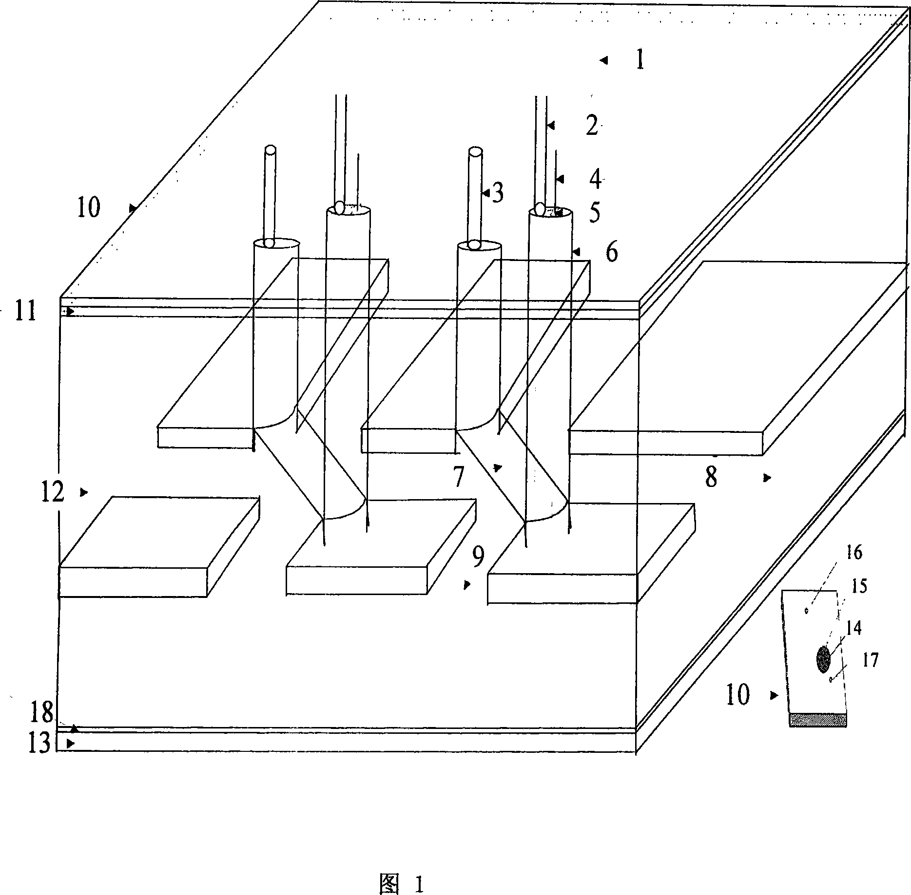
[0031]The present invention provides an electronically controlled array optical switch chip whose structure adopts the structure of "upper cover sheet + insulating layer + waveguide layer + lower cover sheet", wherein the first layer is the upper cover sheet including the cover plate 10, and the There are vent holes 3, liquid injection holes 2 and electrode holes 14 on the top, and a groove 15 made by micro-channel technology at the bottom; the second layer is an insulating layer 11, and a conductive film block 5 is plated on the insulating layer 11, which is conductive The film block 5 is connected to an external control voltage through an electric wire 4. The first small hole 16 and the second small hole 17 on the cover plate 10 correspond to the vent hole 3 and the liquid injection hole 2; the third layer is the optical waveguide layer 12, which is provided The first micro-channel 8 and the second micro-channel 9 are made by the micro-channel process, and the middle part is pro...


PUM


Abstract

The invention discloses a micro flow control array optical switch chip which adopts an 'an upper cover piece + an insulating layer + a wave guiding layer + a base plate' frame, wherein the first layer is the upper cover piece which contains a cover plate (10), a breathing hole (3), a liquid injecting hole (2), and an electrode hole (14) are arranged on the cover plate, a slot (15) which is produced through a micro flow passage process is arranged on bottom portion. The second layer is an insulating layer (11), a little conducting film block (5) is plated on the insulating layer (11), the conducting film block (5) is connected with an outer controlling voltage through an electric lead (4), a first little hole (16) and a little second hole (17) are corresponded with the matching breathing hole (3) and the liquid injecting hole (2). The third layer is an optical waveguide layer (12), a first micro flow passage (8) which is produced by the micro flow passage process and a second micro flow passage (9) are arranged in the optical waveguide layer, a storing slot (6) and a fistula (7) which is traversed through the storing slot are arranged on the middle portion of the third layer. The fourth layer is the base plate (13), a layer of conducting film (18) is arranged on the PDMS of the base plate. The invention has simple structure and easy production, and is applicable for integrating and forming large-scale exchanging matrixes.

Description

Technical field [0001] The invention relates to a microfluidic array optical switch chip structure, belonging to the technical field of optical cross-connection and optical add / drop multiplexing devices in the optical internet. Background technique [0002] Microfluidic optics is a new technology of great significance. It combines modern microfluidic technology and micro-optoelectronics technology to develop a class of optical integrated devices that can adapt to changes in the external environment, have structural reorganization and adaptive adjustment capabilities. The system will have important application prospects in sensing, communication, and other fields. [0003] The microfluidic array optical switch is a two-dimensional integrated device that can realize the integration of optical components and promote the development of micro-optical devices, waveguide devices, and optical integrated devices. This kind of device is widely used in optical communications and many other ...

Claims


Application Information

Patent Timeline
IPC IPC(8): G02B6/35G02B26/02B01L3/00G01N21/00
Inventor 徐宁涂兴华梁忠诚李若梅王雪陈金秋
Owner NANJING UNIV OF POSTS & TELECOMM
Learn More