Phase error detecting apparatus

A phase difference detection and phase error technology, applied in the configuration/installation of the head, instruments, data recording, etc., can solve the problems of unstable tracking servo

Inactive Publication Date: 2008-05-28
PANASONIC CORP
View PDF1 Cites 3 Cited by
  • Summary
  • Abstract
  • Description
  • Claims
  • Application Information

AI Technical Summary

Problems solved by technology

[0031] However, in the conventional method of correcting the DC offset amount of the tracking error signal, the offset correction amount is added even when there is no input signal and no

Method used


Image

  • Phase error detecting apparatus
  • Phase error detecting apparatus
  • Phase error detecting apparatus

Examples


Embodiment 1

[0125] Hereinafter, a phase error detection device according to Embodiment 1 of the present invention will be described.

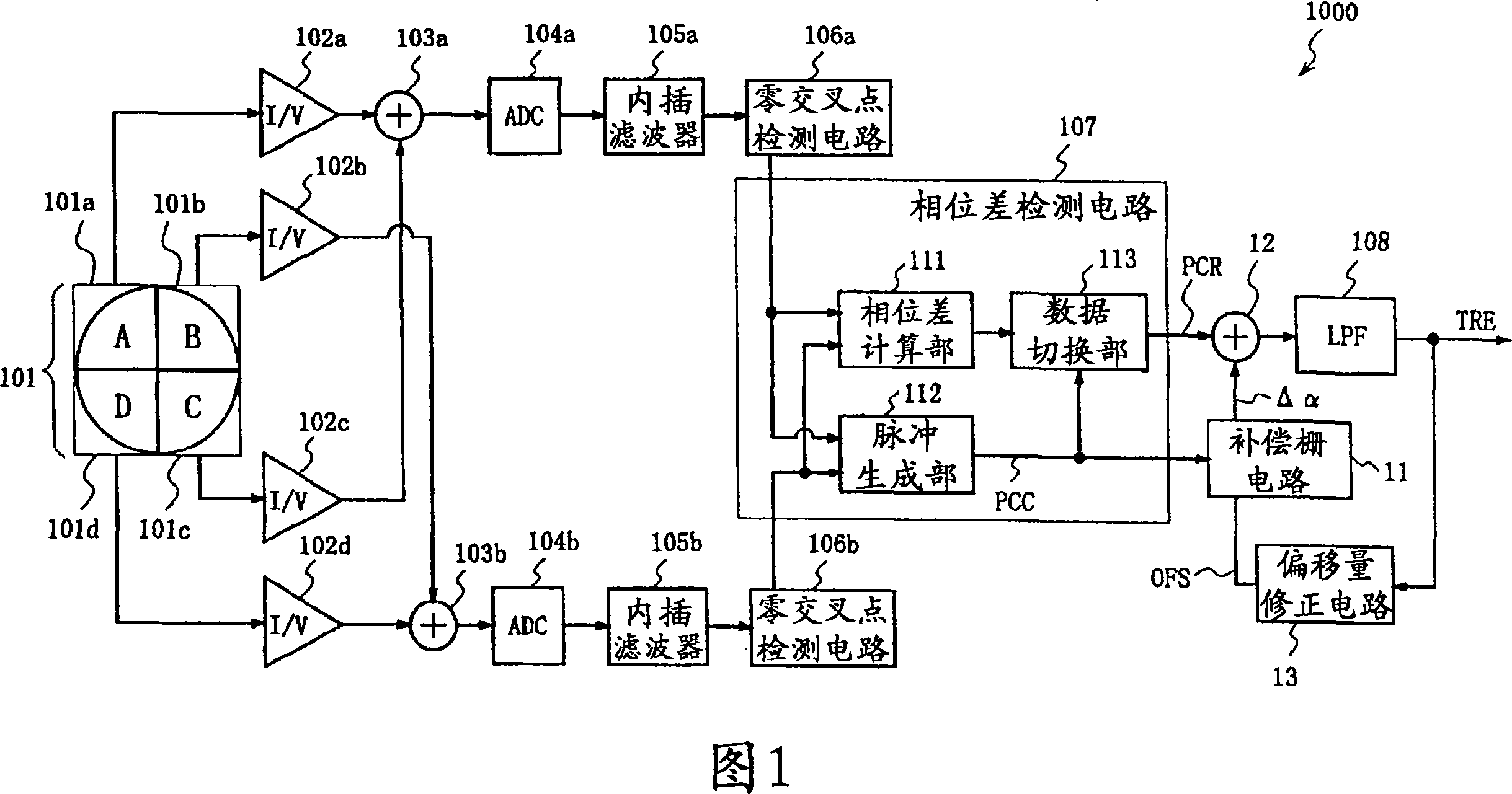
[0126] FIG. 1 is a block diagram showing the structure of a phase error detection device 1000 according to Embodiment 1 of the present invention.

[0127] In FIG. 1 , the phase error detection device 1000 of the present embodiment 1 is configured to include: a photodetector 101 having a photosensitive element that receives reflected light from a light spot, and outputting a photocurrent corresponding to the amount of light received by each photosensitive element; ~ fourth current-voltage converters 102a-102d; signal generators that generate two signal sequences, that is, first and second adders 103a, 103b; first and second analog-to-digital converters (ADC) 104a, 104b; first And the second interpolation filter 105a, 105b; The first and the second zero-cross point detection circuit 106a, 106b; Phase difference detection circuit 107; Low-pass filter (LPF) 10...

Embodiment 2

[0141] Next, a phase error detection device according to Embodiment 2 of the present invention will be described.

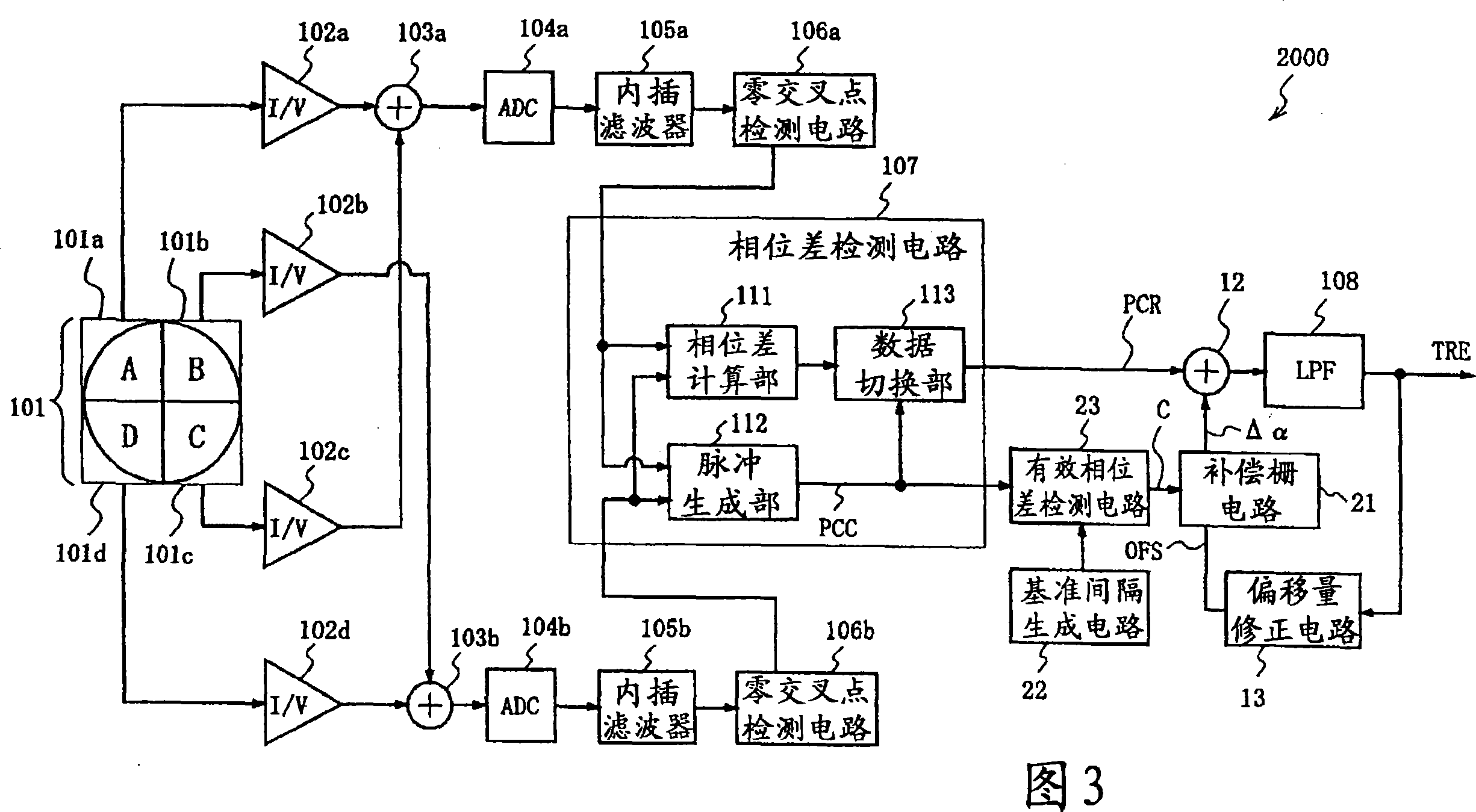
[0142] FIG. 3 is a structural block diagram of a phase error detection device 2000 according to Embodiment 2 of the present invention.

[0143] In FIG. 3 , the phase error detection device 2000 of the present embodiment 2 is configured to include: a photodetector 101 having a photosensitive element that receives reflected light from a light spot, and outputting a photocurrent corresponding to the amount of light received by each photosensitive element; ~ fourth current-voltage converters 102a-102d; signal generators that generate two signal sequences, that is, first and second adders 103a, 103b; first and second analog-to-digital converters (ADC) 104a, 104b; first and second interpolation filters 105a, 105b; first and second zero-cross point detection circuits 106a, 106b; phase difference detection circuit 107; low-pass filter (LPF) 108; third adder 12; circuit ...

Embodiment 3

[0157] Next, a phase error detection device according to Embodiment 3 of the present invention will be described.

[0158] FIG. 5 is a block diagram showing the configuration of a phase error detection device 3000 according to Embodiment 3 of the present invention.

[0159] In Fig. 5, the phase error detection device 3000 of the present embodiment 3 is constituted to include: a photosensitive element having a light receiving reflected light of a light spot, and a photodetector 101 outputting a photocurrent corresponding to the amount of light received by each photosensitive element; First to fourth current-to-voltage converters 102a to 102d that convert the photocurrent output of the detector 101 into voltage signals; obtain first to fourth digital signals from the voltage signals obtained by the first to fourth current-to-voltage converters 102a to 102d The first to fourth analog-to-digital converters (ADC) 104a to 104d for the signal sequence; the first to fourth interpolati...


PUM


Abstract

The present invention provides a phase error detection device capable of correctly performing offset correction of a tracking error signal even when there is a defect or an unrecorded position on an optical disc. Utilize the digital signal of 2 sequences as input, use the distance between the zero-crossing points of the digital signal of this 2 sequences to carry out phase comparison, output the phase difference detection circuit (107) of phase comparison result PCR and phase comparison end signal PCC; A phase comparison end signal PCC from the phase difference detection circuit (107) outputs a compensation gate circuit (11) of the offset correction amount, adds the phase comparison result PCR and the phase comparison result PCR, and does not perform the phase comparison when the phase is not executed. Offset correction for the compared positions.

Description

technical field [0001] The present invention relates to a phase error detection device for detecting a tracking error signal of a light spot obtained by irradiating light onto an optical recording medium. Background technique [0002] As a method of acquiring tracking control signals from optical discs such as CD (Compact Disc) and DVD (Digital Versatile Disc) in which information is recorded with concave and convex pits, a method called phase difference method has been used in recent years. [0003] As an example of the relevant phase difference method, there is a method disclosed in Patent Document 1. [0004] Hereinafter, a conventional phase error detection device 3010 disclosed in Patent Document 1 will be described with reference to FIG. 30 . [0005] FIG. 30 is a block diagram showing the configuration of a conventional phase error detection device 3010 . [0006] As shown in FIG. 30 , a conventional phase error detection device 3010 includes: photosensitive element...

Claims


Application Information

Patent Timeline
IPC IPC(8): G11B7/09
CPCG11B7/094G11B7/0906G11B7/0948
Inventor 坂井满苅田吉博平塚隆繁
Owner PANASONIC CORP
Why Eureka
Try Eureka