Electromagnetic wave shielding laminate and production method therefor

A manufacturing method, electromagnetic wave technology, applied in the direction of magnetic/electric field shielding, electrical components, instruments, etc., can solve the problems of multi-layered manufacturing costs of product structures, defective products, and increased manufacturing processes, so as to prevent the reduction of light transmission and light and thin Improve pass rate and reduce weight load

Inactive Publication Date: 2008-06-04
TOPPAN PRINTING CO LTD
View PDF4 Cites 7 Cited by
  • Summary
  • Abstract
  • Description
  • Claims
  • Application Information

AI Technical Summary

Problems solved by technology

[0009] However, in the conventional method, since various functional layers are attached to the substrate film on which various functional layers should be provided on the electromagnetic wave shielding plate, an adhesive layer must be used for each layer. The reduction of light transmission and the reduction of transparency (increase in Haze value (haze value)) caused by the use of an agent or adhesive, and the use of the base film for each functional layer, therefore, the accompanying weight load and the like become a problem
In addition, when manufacturing a multilayer electromagnetic shielding sheet, the number of manufacturing steps is large, and there are also problems such as an increase in the cause of defective products, a complicated manufacturing process, multi-layered product structure, and manufacturing costs.
[0010] In order to solve the above problems, although it has been thought of laminating the subsequent functional layers on the back of the substrate of the electromagnetic wave shielding plate provided with geometrically shaped copper foil, if it is produced in a full roll (roll-to-roll) When it is manufactured in the same way, the copper foil will be peeled off due to the contact between the roller and the copper foil, or when the blackening treatment is performed, new problems such as peeling will occur in the blackened part, and new problems that must be solved accordingly

Method used


Image

  • Electromagnetic wave shielding laminate and production method therefor
  • Electromagnetic wave shielding laminate and production method therefor
  • Electromagnetic wave shielding laminate and production method therefor

Examples


Embodiment 1

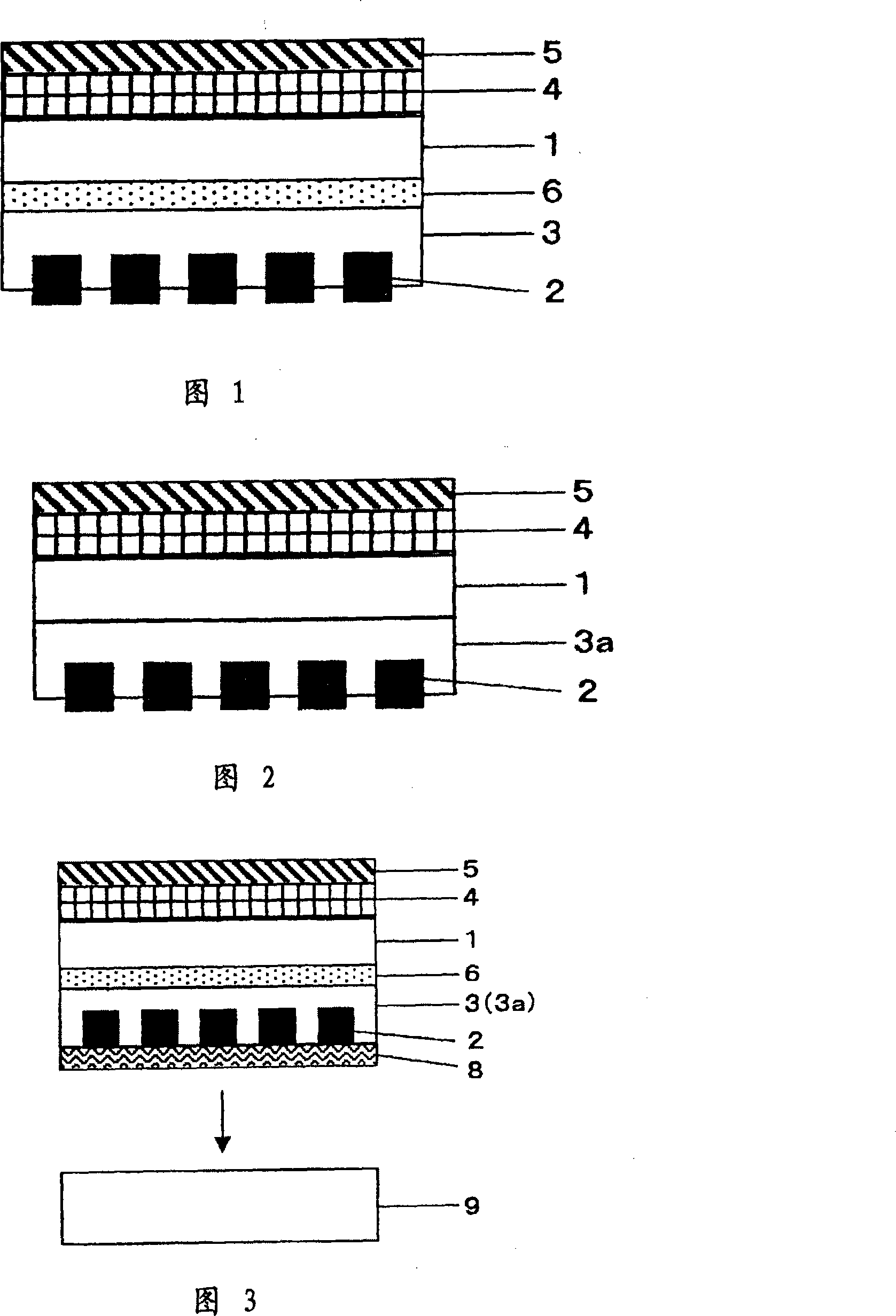
[0239] Use a 100 μm double-sided polyethylene terephthalate film (A-4300: manufactured by Toyobo Co., Ltd.) that has undergone an easy-adhesive treatment as a transfer support. An ultraviolet-curable resin coating solution (AGS102: manufactured by Toyo Ink Manufacturing Co., Ltd.) was applied to about 10 μm (dried film thickness) by a microgravure method as a hard coat layer. On this hard coat layer, LR753 (manufactured by Nippon Kayaku Co., Ltd.) (film thickness: 0.1 μm) was laminated as an antireflection layer. Its visual reflection is 1.0 or less.

[0240] On the back of the hard coat layer of this support, 2 mass parts of near-infrared absorbers (diiminium series and phthalocyanine series) were added to 100 mass parts of acrylic resin (Follett: manufactured by Soken Chemical Co., Ltd.) by the microgravure method. 20 parts by mass of a solvent (dioxolane) and 20 parts by mass of a solvent (dioxolane) to form a near-infrared absorbing layer of about 10 μm (dry film thicknes...

Embodiment 2

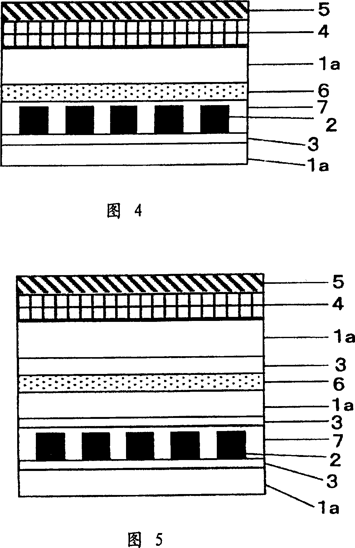
[0246] Use a 100 μm double-sided polyethylene terephthalate film (A-4300: manufactured by Toyobo Co., Ltd.) that has been processed for easy adhesion as a transfer support. An ultraviolet-curable resin coating solution (AGS102: manufactured by Toyo Ink Manufacturing Co., Ltd.) was applied on the upper surface to a thickness of about 10 μm (dry film thickness) by a microgravure method as a hard coat layer. On this hard coat layer, LR753 (manufactured by Nippon Kayaku Co., Ltd.) (film thickness: 0.1 μm) was laminated as an antireflection layer. The visual reflectance thereof is 1.0 or less.

[0247] On the back of the hard coat layer of this support, stick the adhesive surface of the following sheet, that is, the sheet is prepared by adding 100 parts by mass of the second adhesive or adhesive BPS5296 (manufactured by Toyo Ink) on the separator. Among them, a coating solution composed of 2 parts by mass of a near-infrared absorber (diiminium-based and phthalocyanine-based) and 2...


PUM


Abstract

The present invention relates to a method for producing an electromagnetic wave shielding laminate, comprising the following steps: a step of forming a geometrically shaped electromagnetic wave shielding material on a peelable support; peeling the electromagnetic wave shielding material from the peelable support; The process above the support for transfer, wherein the support for transfer has one or more layers having conductivity, anti-reflection, reduced reflectivity, hard coat properties, anti-glare properties, anti-glare properties on one side or both sides of the film. A functional layer with one or more functions among contamination function, near-infrared absorption function, ultraviolet absorption function, color correction function, heat dissipation function, de-neon function, scattering prevention function, and shock-resistant buffer function.

Description

technical field [0001] The present invention relates to a laminate that is transparent and has electromagnetic wave shielding function and other functions, and can be preferably used as a display front panel of a display such as a CRT or plasma display panel, a fluorescent display tube, an electric field emission display, and a method for manufacturing the same. Background technique [0002] In recent years, there has been a problem of leakage of electromagnetic waves (microwaves) from various displays such as CRTs and plasma displays, electronic devices, and the like. Therefore, an electromagnetic wave shielding sheet is attached to the front of the display to shield electromagnetic waves leaking from the display. Since the electromagnetic wave shielding sheet is installed in front of the display, it is required to have both electromagnetic wave shielding properties and transparency. From this point of view, an electromagnetic wave shielding sheet with better electromagneti...

Claims


Application Information

Patent Timeline
Patent Type & Authority Applications(China)
IPC IPC(8): H05K9/00G09F9/00
CPCH05K9/0096H05K9/00
Inventor 加藤茂干德留一人井手吉范文鹤田智博薄井慎一町田敏则中村尚稔上田幸弘
Owner TOPPAN PRINTING CO LTD
Why Eureka
Try Eureka