
Injection molding method for thermoplastic resin

A thermoplastic resin, injection molding technology, used in the field of injection molding, can solve the problems of uneven shrinkage, carbon dioxide can not evenly penetrate the surface layer, increase molding cost, etc., and achieve improved reproduction and gloss, excellent reproduction and gloss. Effect

Inactive Publication Date: 2008-06-11
宗形株式会社
View PDF2 Cites 2 Cited by
  • Summary
  • Abstract
  • Description
  • Claims
  • Application Information

AI Technical Summary

Problems solved by technology

[0003] However, in this method, although the reproducibility is improved, shrinkage cavities (ヒケ) and warpage tend to occur in the molded product due to uneven shrinkage when the resin is cured
And the following problems arise: the molding cycle becomes longer, the production efficiency is lowered, and thus the molding cost is increased
However, these methods have the following problems: Although the reproducibility is improved, special equipment is required for each, and the molding cost is increased because the molding cycle becomes longer and the production efficiency is lowered.
[0009] However, in the invention described in the aforementioned Japanese Patent Laid-Open No. 2000-244610, when the thickness of the molded article is thin or the shape is complex, there may be a transfer defect as follows: the carbon dioxide does not permeate the surface layer uniformly, and the transfer cannot be improved as a whole. , or cannot locally improve replicability
As one of the reasons, the problem is that after the filling process of the molten resin is completed, the molten resin in the cavity of the mold remains under the high resin pressure during filling, and even if carbon dioxide is injected, the injected carbon dioxide cannot be sufficiently spread to be compatible with the entire product. Between the cavity surface corresponding to the viewing surface and the molten resin

Method used


Image

  • Injection molding method for thermoplastic resin
  • Injection molding method for thermoplastic resin
  • Injection molding method for thermoplastic resin

Examples


Embodiment 1

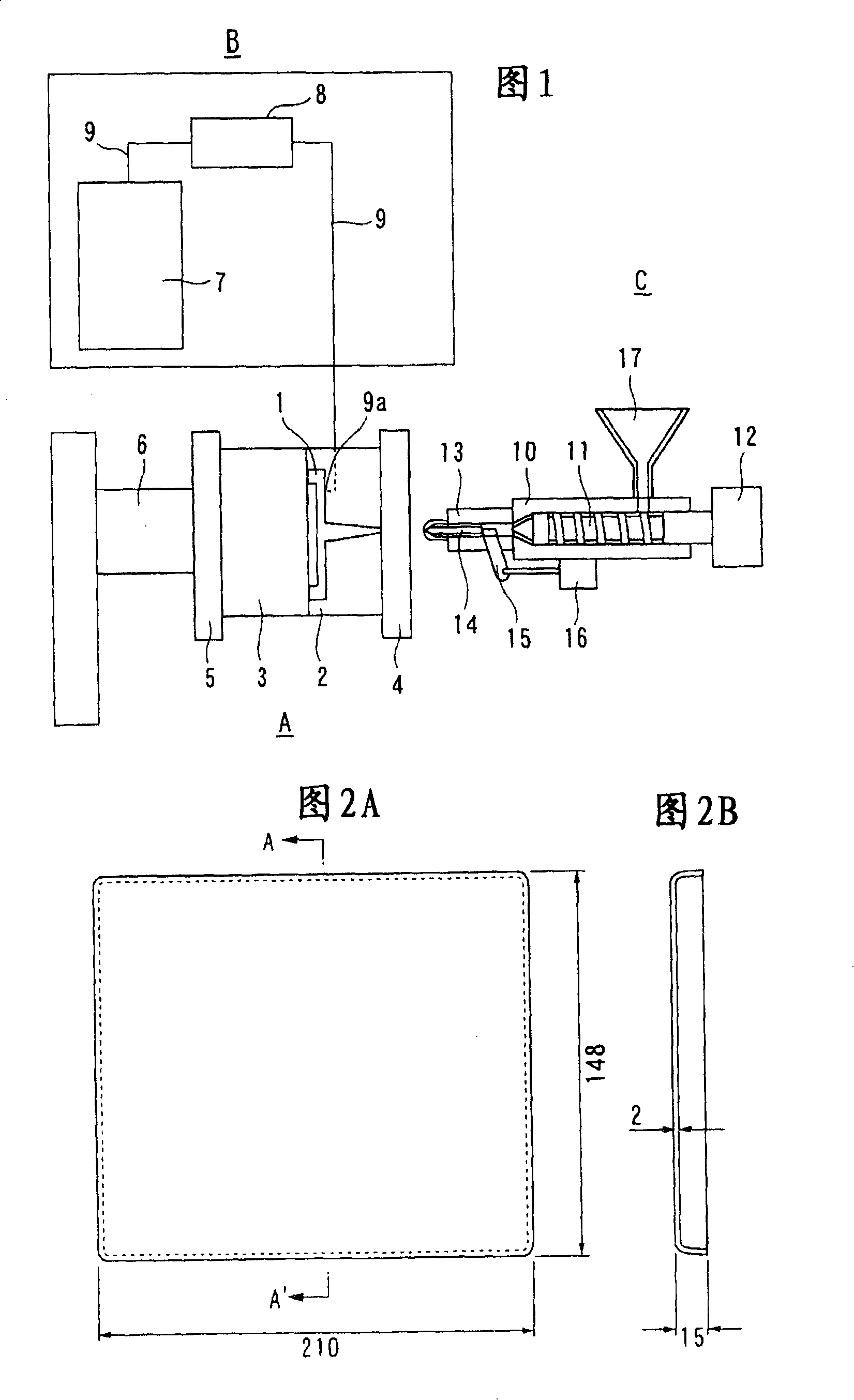
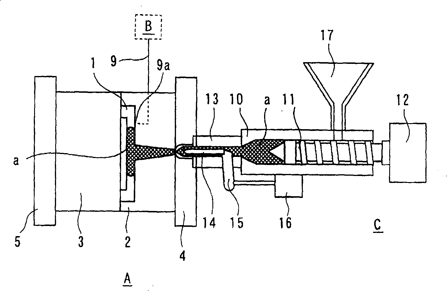
[0035] Fig. 1 is an overall view showing a molding device A, a carbon dioxide injection device B and a resin filling device C in an injection molding machine for carrying out the present invention. Reference numeral 1 is a mold cavity formed by clamping the fixed side mold 2 and the movable side mold 3 in the injection molding device A, 4 is a fixed side mold plate, 5 is a movable side mold plate, and 6 is a mold plate position adjustment device.

[0036] In the carbon dioxide injection device B, 7 is a high-pressure carbon dioxide generator that generates high pressure, 8 is a carbon dioxide injection unit, and 9 is a piping that connects the high-pressure carbon dioxide generator 7 and the carbon dioxide injection unit 8 and the injection unit 8 and the mold cavity 1 The injection ports 9a are connected, and carbon dioxide can be injected into the visible surface side of the cavity 1 from the piping 9 .

[0037] In the resin filling device C, 10 is a cylinder, 11 is a screw in...

Embodiment 2

[0044] This embodiment 2 corresponds to the invention described in claim 3. In embodiment 2, after the filling process is completed, when the resin discharge port at the tip of the nozzle part 13 is closed while the stop pin 14 is kept advancing, the screw 11 is advanced, After increasing the resin pressure on the tip side of the screw 11 inside the barrel 10 and maintaining it, as Figure 5 As shown, by driving the shut-off operation control device 16, the discharge port of the nozzle part 13 is opened, and the molten resin a maintained at high pressure flows into the cavity 1 of the mold at one stroke, and the same as in the first embodiment except that take shape. As a result, a good molded article having a glossiness of 85, excellent reproducibility, and 100% of the evaluated area was reproduced was obtained.

Embodiment 3

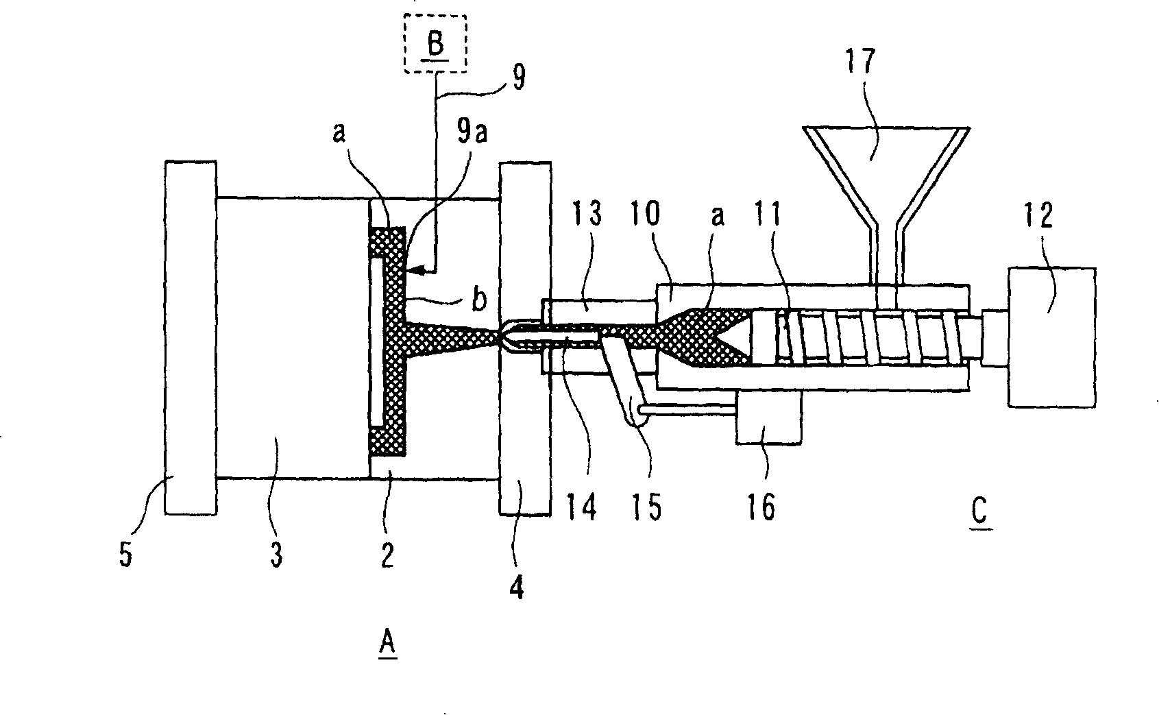
[0050] Present embodiment 3 corresponds to the invention described in technical solution 4. In embodiment 1, after the filling process of molten resin is completed, start from the position of driving the flow-cutting operation control device 16 to stop and hold the screw rod 11, as Figure 6 As shown, the mold plate 5 was retracted by 0.01mm, the movable mold 3 was slightly opened 1a, the resin pressure in the cavity 1 was lowered, and carbon dioxide was injected, and molding was carried out in the same manner. As a result, the glossiness of the obtained molded article was 80, and a good molded article excellent in reproducibility and free from partial reproducibility defects could be obtained. In the evaluation area on the visible surface side, the reproduction of the area ratio area of ​​100% can be improved.

[0051] In addition, the examples 1 to 3 are described by taking only carbon dioxide injected into the mold cavity 1 as an example, but it is also possible to inject m...


PUM


Abstract

The invention provides an injection molding method capable of further increasing the replicability and glossiness during the injection molding of carbon dioxide. The method of injection molding includes that resin (a) is filled in a die cavity (1), then in the process from the starting to die opening, the replicability and the glossiness are increased by injecting the carbon dioxide between the resin and the surface of the die cavity, wherein after a filling procedure that the resin with a just-designed amount is filled in the die cavity is finished, a procedure aiming to decrease the pressure of the resin through temporarily stopping the filling of the resin is provided, and then a pressure keeping procedure is carried out by increasing the pressure of the resin. The carbon dioxide can be uniformly distributed everywhere in the cavity (1) through employing the method, and thereby the replicability and the glossiness of the integral visual surface of molding products can be uniformly increased.

Description

technical field [0001] The present invention relates to an injection molding method for thermoplastic resins, and more specifically to an injection molding method as follows: in order to improve reproducibility (writing property) and glossiness, carbon dioxide, etc. The surface softens and enters the holding process, thereby improving reproducibility and gloss. Background technique [0002] In general, injection molding is to fill the molten resin into the cavity of the mold and cool it in the mold to obtain the molded product. In this injection molding, the mold is kept below the solidification temperature of the resin before filling the resin. Therefore, the solidification of the resin proceeds from the moment the molten resin is filled into the cavity, and a solidified layer called a skin layer is formed on the surface. In particular, the flow front of the molten resin is replicated on the surface of the molded article due to the action of the fountain flow. Curing also...

Claims


Application Information

Patent Timeline
IPC IPC(8): B29C45/17B29C45/77B29C45/76C08J5/00
CPCB29C45/174
Inventor 馆山弘文海野雄士
Owner 宗形株式会社
Learn More