Vane type cavity capability changing device, vane type gas engine and vane compressor
A vane type, inner ring technology, which is applied in the field of the device where the piston performs rotary motion in the cylinder, can solve the problems of poor mechanical balance, affecting the service life, large weight of the left and right vanes, etc., and achieves a small number of parts and high work efficiency. , the effect of high blade strength
- Summary
- Abstract
- Description
- Claims
- Application Information
AI Technical Summary
Problems solved by technology
Method used
Image
Examples
Embodiment 1
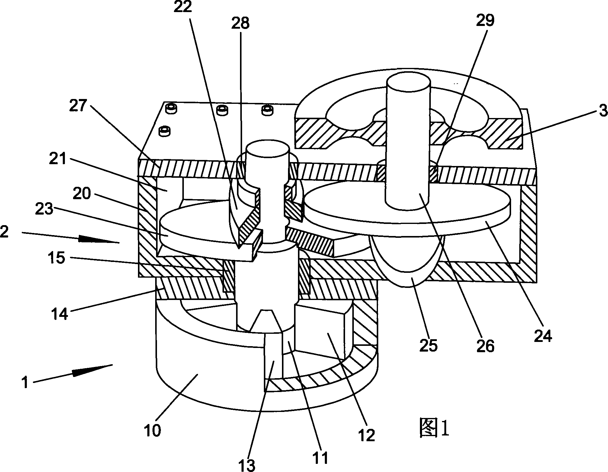
[0063] The structure of an embodiment of the vane-type variable cavity volume device of the present invention is shown in FIG. 1. The vane-type variable cavity volume device has a cylinder 1, a transmission box 2 and a flywheel 3.
[0064]The first group of pistons 12 and the second group of pistons 13 are installed coaxially and alternately in the annular revolving space 11 in the circular box-shaped cylinder body 10 of the cylinder 1.
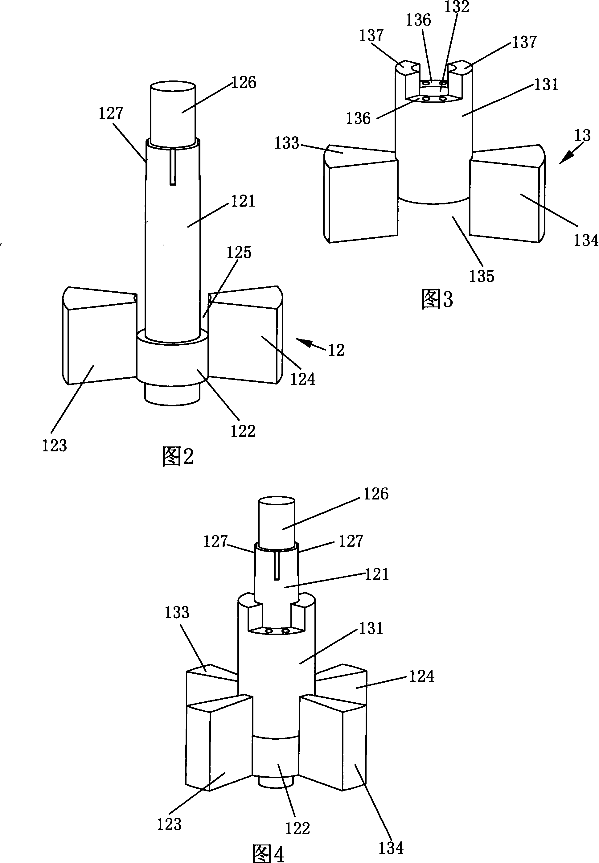
[0065] For the structure of the first group of pistons 12, please refer to Figure 2: The lower part of the rotation shaft 121 of the first group of pistons 12 is provided with a ring-shaped flange 122, and the two flanges 122 are fixedly connected to each other in the radial direction on the outer circumferential surface. The lower half of the inner end surfaces of two rectangular blades 123 and 124, the upper half of the inner end surfaces of the two blades 123 and 124, the outer circumferential surface of the rotating shaft 121 and the upper en...
Embodiment 2
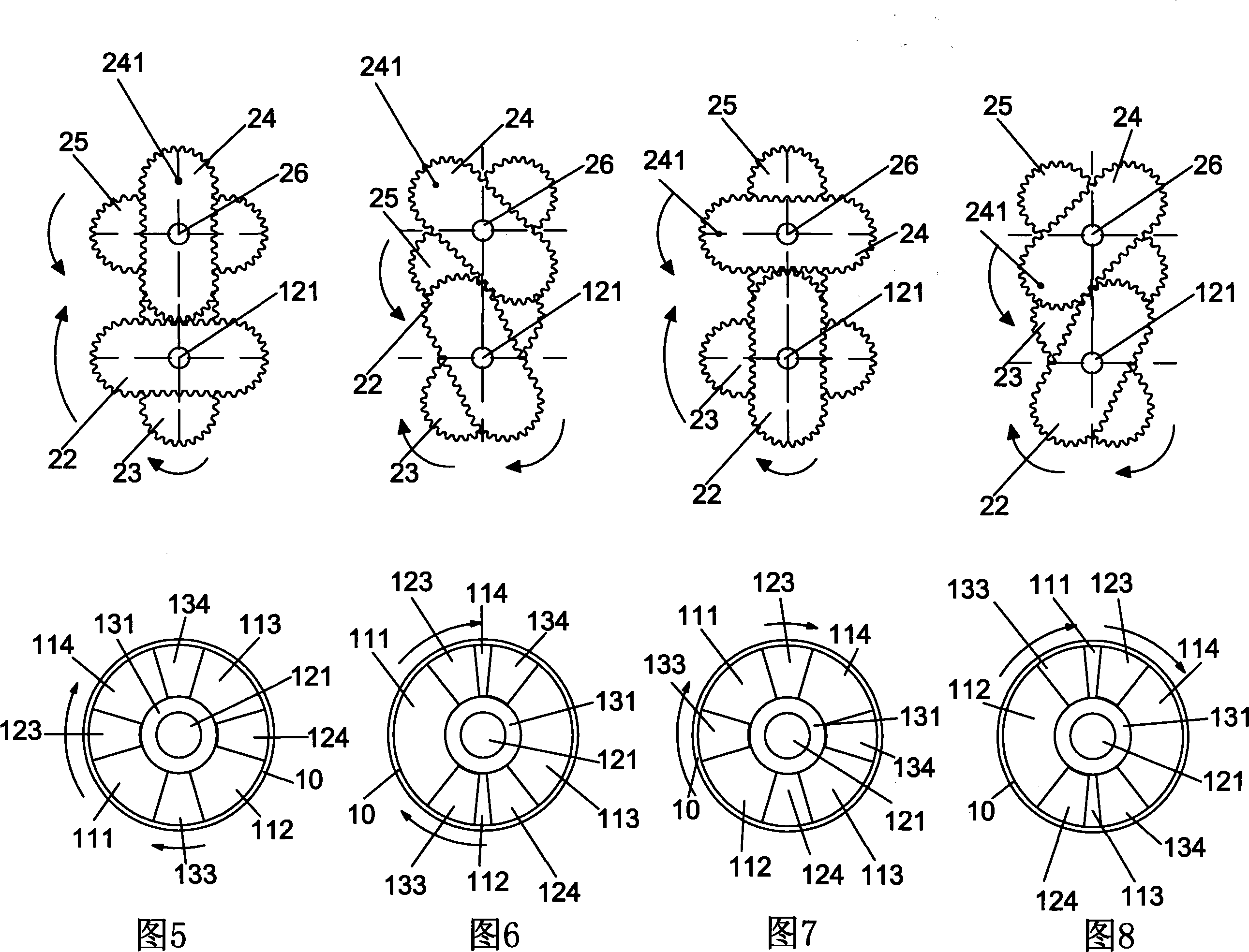
[0084] An embodiment of the vane type internal combustion engine of the present invention adopts the vane type variable cavity volume device shown in FIG. 1. The difference between the structure of the vane-type internal combustion engine embodiment and the vane-type variable cavity volume device of the previous embodiment is that the air inlets 4, 4 are respectively arranged in the annular revolving space 11 in the cylinder block 10 at the position of 7:15. The exhaust port 5 is set at the position of 4:3 and the igniter 6 is set at the position of the zero point; the transmission shaft 26 is the power output shaft. The structure of the vane-type variable cavity product device shown in FIG. 1 and the meshing rotation of the two oblong gears 22, 23 and the four working chambers 111, 112 during the uniform angular velocity rotation of the two oblong gears 24, 25 on the transmission shaft 26 The volume changes of 113, 114 have been described in detail in the previous description, li...
Embodiment 3
[0100] One embodiment of the vane type compressor of the present invention adopts the vane type variable cavity volume device shown in FIG. 1. The difference between the structure of the vane type compressor embodiment and the vane type variable cavity volume device of the first embodiment is that the first air intake is set in the annular revolving space 11 in the cylinder block 10 at the position of 7:15. Port 4', a first exhaust port 5'is set at the zero position; a second intake port 4" is set at the one-and-a-minute position and a second exhaust port 5" is set at the six o'clock position. The structure and power input shaft of the vane-type variable cavity product shown in Fig. 1-the meshing rotation of the two oblong gears 24 and 25 on the transmission shaft 26 during one round of uniform angular velocity rotation and the four oblong gears 22 and 23 The volume changes of the working chambers 111, 112, 113, and 114 have been described in detail in the previous description; du...
PUM
 Abstract
Description
Claims
Application Information
 - R&D
- Intellectual Property
- Life Sciences
- Materials
- Tech Scout
- Unparalleled Data Quality
- Higher Quality Content
- 60% Fewer Hallucinations
Browse by: Latest US Patents, China's latest patents, Technical Efficacy Thesaurus, Application Domain, Technology Topic, Popular Technical Reports.
© 2025 PatSnap. All rights reserved.Legal|Privacy policy|Modern Slavery Act Transparency Statement|Sitemap|About US| Contact US: help@patsnap.com


