Method for parallel light directly beaming parallel light or focusing light and high-energy high stream intensity device

A technology of parallel light and focused light, which is applied in solar energy concentration methods and devices, and in the field of optics. It can solve the problems of size, weight, and process that are difficult to achieve high energy, long-distance transmission, and restrictions on the large-scale and effective use of solar energy. Simple, optical surface shapes for simple effects

Inactive Publication Date: 2008-06-11
吴荣久
View PDF0 Cites 13 Cited by
  • Summary
  • Abstract
  • Description
  • Claims
  • Application Information

AI Technical Summary

Problems solved by technology

[0003] At present, the existing methods mainly focus on heat collection such as parabolic mirror lenses, and its disadvantage is that it is difficult to achieve high-energy, long-distance transmission due to limitations in size, weight, and technology.
[0004] In recent years, the combination of l

Method used


Image

  • Method for parallel light directly beaming parallel light or focusing light and high-energy high stream intensity device
  • Method for parallel light directly beaming parallel light or focusing light and high-energy high stream intensity device

Examples


Embodiment 1

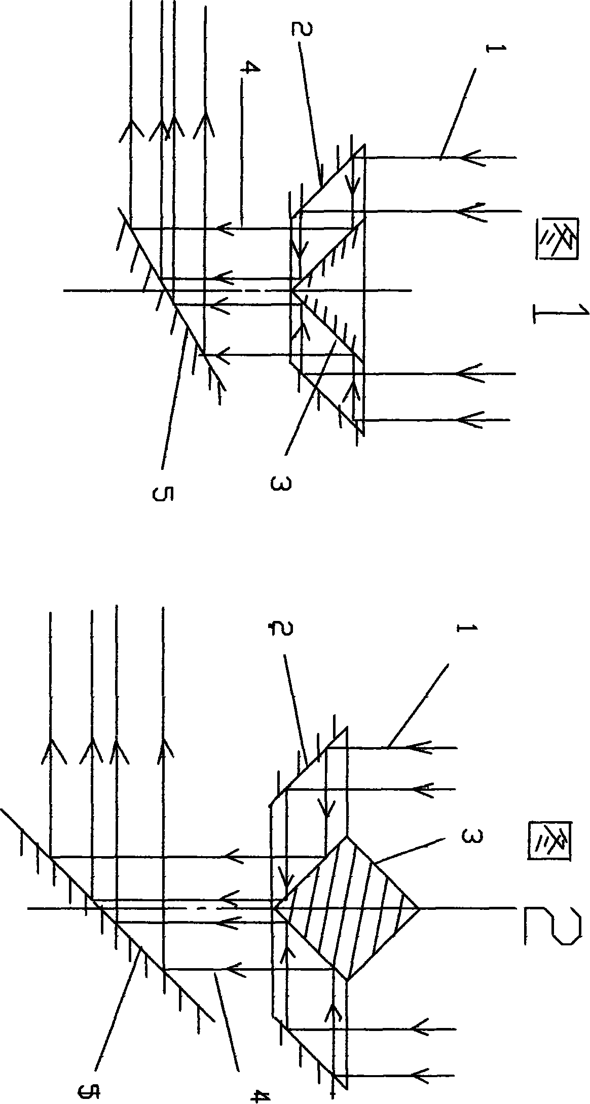
[0043] As shown in Figure 1, the present invention uses the inner surface of the outer cone 2 to reflect the sunlight 1 incident along the axis onto the outer surface of the inner cone 3, and then reflects and bundles it directly into parallel light or focused light 4 for output. The output direction is the same as the incident direction In the same way, the output and output transmission direction of the system is sent to the user through the control of the plane reflector.

Embodiment 2

[0045] As shown in Figure 1, the present invention adopts the inversion of the inner cone 3 and the other conditions remain unchanged. The sunlight 1 incident along the axis is reflected by the reflective surface of the outer cone 2 to the reflective surface of the inner cone 3 to reflect and directly gather parallel light or focused light output, and the output direction is the same as that of the focused light. The input direction is opposite, and the output transmission direction system is sent to the user through the plane reflector control system.

Embodiment 3

[0047]As shown in Figure 2, the present invention uses double cones to replace the inner cone 3 in Figure 1 to increase the system for controlling the movement of the double cones along the axis. Figure 2 At this moment, the output parallel light or focused light beam 4 of the lower cone that hits the double cone 3 is transmitted downward. When the double cone is moved downward, part of the reflective area that enters the outer cone 2 from the upper part of the double cone 3 is bundled into parallel light or focused When the light is output from the upper side, it is a two-way output. When the double cone 3 continues to move down until the lower part just moves out, there is only an upward reverse output. All output is sent to the user through the plane mirror control output transmission direction system.


PUM


Abstract

The invention discloses a method for bundling the parallel light to parallel light or focusing light, and a device for gaining high energy and high beam current, which belongs to the technical field of optics, especially the field of solar application. The method is to realize direct bundling from the parallel light to parallel light or focusing light by the direct bundling function of the reflective panel combination of double positive cones which are appropriately fixed and form a direct bundling (parallel light or focusing light) device of the parallel light with the sunshine tracking system and output transmission directional system controlled by plane mirror, which is used for heating, food and beverage, disinfection, etc. A re-bundling system is formed by the appropriate combination of the bundling method provided in the invention and other bundling methods (parabolic mirror and lens, large lens and small lens, large and small parabolic mirror, etc.) to gain a high energy and high beam current device used for welding, cutting and blinding by scanning or functioned as other military attack, etc. Simultaneously inject a plurality of parallel light directly bundling devices into a fixed (without tracking system) parallel light directly bundling device from parallel light, and gain the high energy by rebuilding used for metallurgy and power generation, etc. In the same way, simultaneously inject a plurality of laser beam into a fixed (without tracking system) parallel light or focusing light directly bundling device from parallel light to gain high-energy laser beam by rebuilding used for industry or national defense.

Description

technical field [0001] The invention belongs to the field of optical technology, in particular to the field of solar energy concentrating methods and devices. Background technique [0002] Due to the danger of depletion of traditional energy materials, coal, oil, and gas and its pollution to the human living environment, human beings are eager to find green energy that can be used for a long time and is environmentally friendly. Since solar energy is inexhaustible and non-polluting, it has become the first choice. , all countries in the world are trying their best to find effective collection and utilization methods. [0003] At present, the existing methods mainly focus on heat collection such as parabolic mirror lenses. The disadvantage is that it is difficult to achieve high-energy and long-distance transmission due to limitations in size, weight, and technology. [0004] In recent years, the combination of large parabolic mirror-small parabolic mirror, parabolic mirror-...

Claims


Application Information

Patent Timeline
IPC IPC(8): G02B17/06G02B17/08
Inventor 吴荣久
Owner 吴荣久
Why Eureka
Try Eureka