Composite materials
A technology of composite materials and alloys, applied in the direction of abrasives, polishing compositions containing abrasives, and other chemical processes, can solve the problems of poor rigidity of the matrix
- Summary
- Abstract
- Description
- Claims
- Application Information
AI Technical Summary
Problems solved by technology
Method used
Image
Examples
Embodiment 1
[0072] Example 1 - Hardfacing Decals for Rock Breaker Faces
[0073] Hard Particle Component: Coarse-grained tungsten carbide, titanium carbide, zirconium carbide, zirconia, tantalum carbide, niobium carbide, hafnium carbide comprising from about 20% to about 97% by weight of the composite and having an average particle size of from about 5 microns to about 10,000 microns , chromium carbide, vanadium carbide and / or crushed cemented carbide.
[0074] Carrier Component: Fugitive polymer comprising from about 1% to about 20% by weight and providing complete burnout during initial heating of the applique.
[0075] Additive: From about 0% to about 50% by weight copper-based braze alloy.
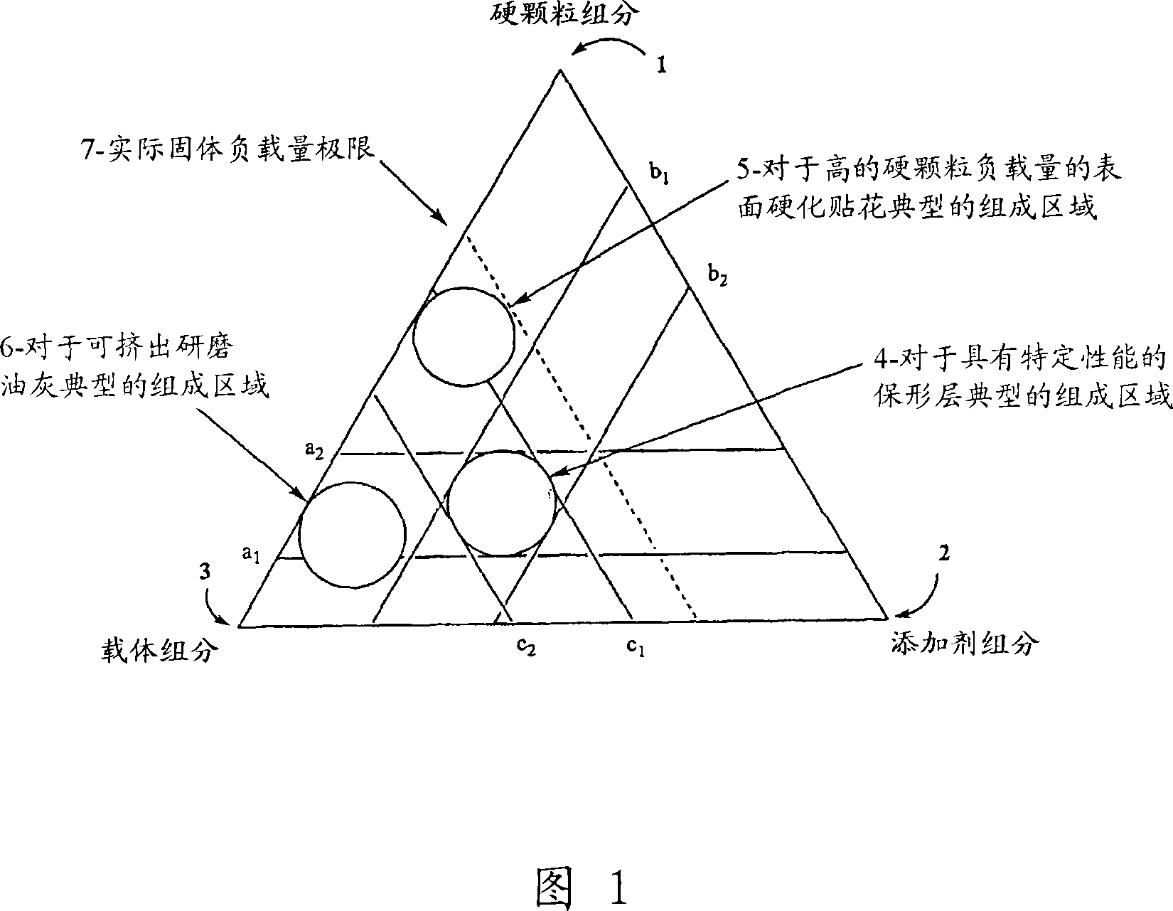
[0076] The density of the applique is preferably relatively high, at 2 g / cm due to the high loading of the hard particle component 3 to about 10g / cm 3 range and generally close to or exceed the calculated solid limit, as shown by the dashed line 7 in Fig. 1. The composite is in the form of a s...
Embodiment 2
[0077] The preparation of the wearing surface of embodiment 2-metalworking tool
[0078] Hard Particle Component: Coarse grained tungsten carbide comprising from about 20% to about 97% by weight of the composite material and having an average particle size of from about 5 microns to about 10,000 microns.
[0079] Carrier Component: A fugitive elastomer comprising from about 1% to about 20% by weight and providing complete burnout during initial heating of the wear surface.
[0080] Additives: Transition metal based brazing alloys such as cobalt-, Ni-Co or Ni-Cu based brazing alloys or titanium alloys are typical, but more expensive Ag based brazing alloys may also be used. The transition metal-based braze alloy comprises from about 0% to about 50% by weight of the composite.
[0081] The density of the applique is preferably relatively high, at about 2 g / cm due to the high loading of the hard particle component 3 to about 10g / cm 3 range and generally close to or exceed the ...
Embodiment 3
[0082] Example 3 - Extrudable Grinding Putty
[0083] Hard Particle Component: Medium particle tungsten carbide comprising from about 0% to about 98% by weight and having an average particle size of from about 2 microns to about 5 microns.
[0084] Carrier Component: A polymer comprising from about 2% to about 50% by weight and providing a controlled and relatively constant viscosity.
[0085] Additives: 0% to about 30% by weight of stabilizers such as UV stabilizers and colorants for identification. Must be compatible with the specified carrier and generally readily available within the plastics industry.
[0086] Due to the presence of hard particles, the density of the putty is preferably medium, at about 2 g / cm 3 to approximately 8g / cm 3 within range. The putty is preferably extrudable at low pressures, ie, less than 689.5 kPa (100 psi), and is resistant to flow separation. The putty is also preferably non-corrosive, has low toxicity, and is easily recyclable.
PUM
| Property | Measurement | Unit |
|---|---|---|
| particle size | aaaaa | aaaaa |
| thickness | aaaaa | aaaaa |
| particle size | aaaaa | aaaaa |
Abstract
Description
Claims
Application Information
 - R&D
- Intellectual Property
- Life Sciences
- Materials
- Tech Scout
- Unparalleled Data Quality
- Higher Quality Content
- 60% Fewer Hallucinations
Browse by: Latest US Patents, China's latest patents, Technical Efficacy Thesaurus, Application Domain, Technology Topic, Popular Technical Reports.
© 2025 PatSnap. All rights reserved.Legal|Privacy policy|Modern Slavery Act Transparency Statement|Sitemap|About US| Contact US: help@patsnap.com


