Pressing type sludge dehydration apparatus and working method thereof

A sludge dehydration and sludge technology, applied in the direction of dehydration/drying/concentrated sludge treatment, etc., can solve difficult problems such as reducing the water content of sludge, achieve good dehydration effect, prevent and control environmental pollution, and have reasonable design effects

Inactive Publication Date: 2008-06-18
大连达翔环保科技工程有限公司
View PDF0 Cites 23 Cited by
  • Summary
  • Abstract
  • Description
  • Claims
  • Application Information

AI Technical Summary

Problems solved by technology

Due to the small size of sludge particles, it is difficult to reduce the water content of sludge from 80% to 40%-50% by direct filtration and dehydration.

Method used


Image

  • Pressing type sludge dehydration apparatus and working method thereof

Examples


Embodiment 1

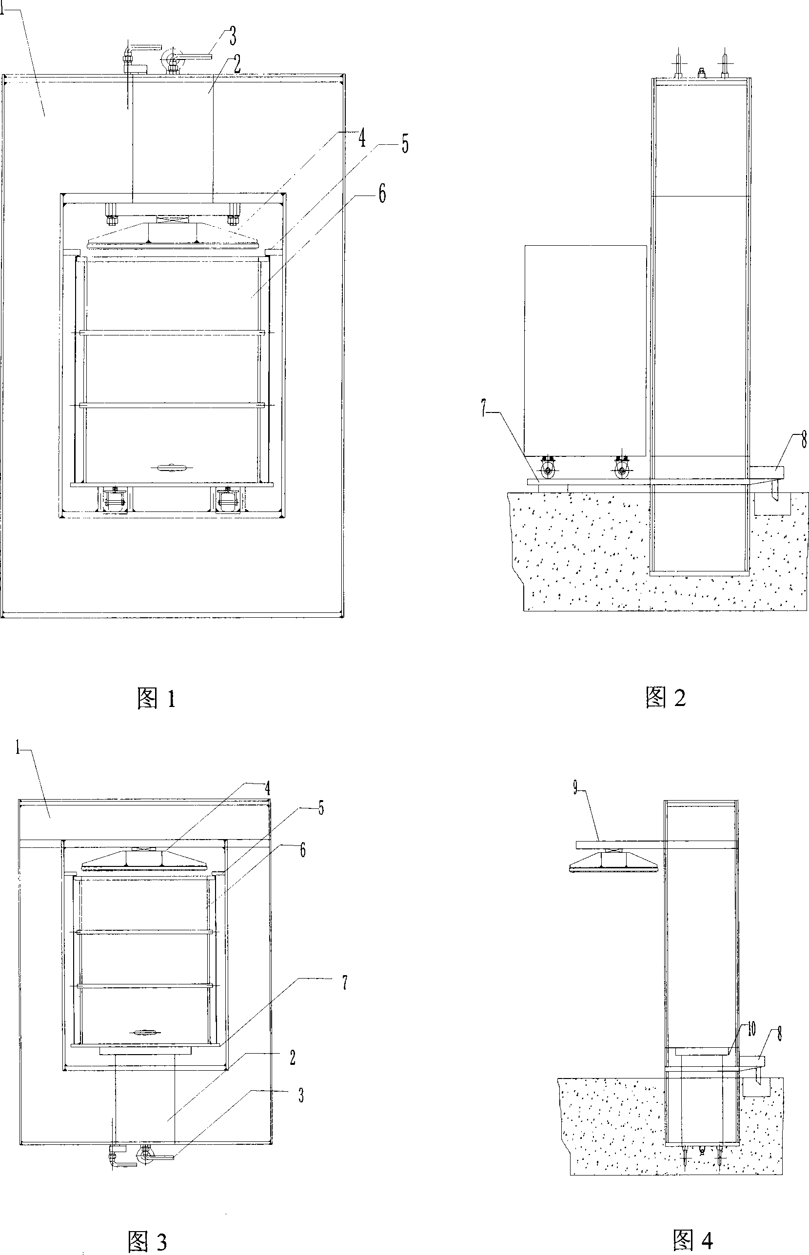
[0023] Structure of the present invention as shown in Figure 1 and Figure 2, comprises frame 1, material cylinder 6 and hydraulic oil cylinder 2, and material cylinder 6 and hydraulic oil cylinder 2 are all installed on the frame, and hydraulic oil cylinder 2 is positioned at above material cylinder 6; The cylinder 6 is a cylindrical material cylinder, the upper end of the material cylinder 6 is open, the lower end is sealed, and the water outlet holes are distributed on the side wall of the material cylinder; the upper end of the material cylinder 6 is provided with a pressure plate 4 that matches the inner diameter of the material cylinder 6, and the back of the pressure plate 4 is connected to the hydraulic pressure. The piston of oil cylinder 2 is fixedly connected.

[0024] The frame 1 is provided with a positioner 5 , and the positioner 5 is located between the material cylinder 6 and the pressing plate 4 .

[0025] The material cylinder 6 is installed on the chassis 7 o...

Embodiment 2

[0035] Structure of the present invention as shown in Figure 3 and Figure 4, comprises frame 1, material cylinder 6 and hydraulic oil cylinder 2, and material cylinder 6 and hydraulic oil cylinder 2 are all installed on the frame, and hydraulic oil cylinder 2 is positioned at material cylinder 6 below; The cylinder 6 is a cylindrical material cylinder, the upper end of the material cylinder 6 is open, the lower end is sealed, and the water outlet holes are distributed on the side wall of the material cylinder; Skateboard 9 links to each other.

[0036] The frame 1 is provided with a positioner 5 , and the positioner 5 is located between the material cylinder 6 and the pressing plate 4 .

[0037] The material cylinder 1 is installed on the chassis 7 of the frame 1, and the material cylinder 6 can move in the horizontal direction of the chassis 7; the upper part of the material cylinder 6 is provided with a feeding port.

[0038] The bottom of the material cylinder 6 is provide...


PUM

PropertyMeasurementUnit
water contentaaaaaaaaaa

Abstract

The invention relates to a squeezing type sludge dehydrating device and operation method, belonging to a technical field of sludge dehydrating device. The device comprises a housing, a material vat, and a hydraulic cylinder, wherein the material vat and the hydraulic cylinder both are arranged on the housing, the hydraulic cylinder is arranged above or below the material vat; the material vat is cylindrical, the upper end of the material vat is open and the lower end is closed, water outlet holes are distributed on sidewalls of the material vat; the upper end of the material vat is provided with a press plate that is matched with the inner diameter of the material vat, the back of the press plate is connected with the piston of the hydraulic cylinder or the slide plate at the upper part of the housing, the housing is provided with a locator, the material vat is arranged fixedly on the chassis of the housing, the upper part of the material vat is provided with a material inlet; a water baffle disc is arranged at the bottom of the material vat; the hydraulic cylinder is provided with a hydraulic oil pipe, when the hydraulic cylinder is started, the piston of the hydraulic cylinder drives the press plate to move in the material vat or drives the material vat to move upwardly, so as to apply force on the sludge in the material vat, when the sludge in the material vat is squeezed by the press plate repeatedly , the water content of the sludge is reduced.

Description

technical field [0001] The patent of the present invention relates to a press-type sludge dewatering device and its working method, belonging to the technical field of sludge dewatering devices. Background technique [0002] The treatment of various domestic and industrial sludge such as municipal sludge, papermaking sludge, printing and dyeing sludge, and chemical sludge is a difficult problem in the field of environmental science and engineering. Incineration technology is by far the best sludge treatment method. A key premise of incineration technology is sludge dehydration and drying, reducing the water content of sludge from 80% to 40%-50%, making full use of the calorific value in sludge in the incineration process, and replacing coal as a fuel for combustion. Due to the small size of the sludge particles, it is difficult to reduce the water content of the sludge from 80% to 40%-50% by direct filtration and dehydration. Contents of the invention [0003] Aiming at t...

Claims


Application Information

Patent Timeline
Patent Type & Authority Applications(China)
IPC IPC(8): C02F11/12
Inventor 刘丰卢庆亮李晓俊李静张承志赵洪成马晋平
Owner 大连达翔环保科技工程有限公司
Why Eureka
Try Eureka