Reaction chamber inner lining and reaction chamber containing the inner lining

A reaction chamber and lining technology, applied in gaseous chemical plating, coatings, electrical components, etc., can solve the problems of unstable local gas pressure, uneven plasma distribution, affecting the results of the etching process, etc. Effect of uniformity, improved uniformity, uniform etch rate

Active Publication Date: 2008-06-18
BEIJING NAURA MICROELECTRONICS EQUIP CO LTD
View PDF0 Cites 22 Cited by
  • Summary
  • Abstract
  • Description
  • Claims
  • Application Information

AI Technical Summary

Problems solved by technology

However, in the existing reaction chamber, due to the design of the gas injection and pumping methods, the air flow in the chamber must undergo changes in flow velocity and direction, which causes instability in the local gas pressure
In order not to affect the process, the cross-...

Method used


Image

  • Reaction chamber inner lining and reaction chamber containing the inner lining
  • Reaction chamber inner lining and reaction chamber containing the inner lining
  • Reaction chamber inner lining and reaction chamber containing the inner lining

Examples


Embodiment Construction

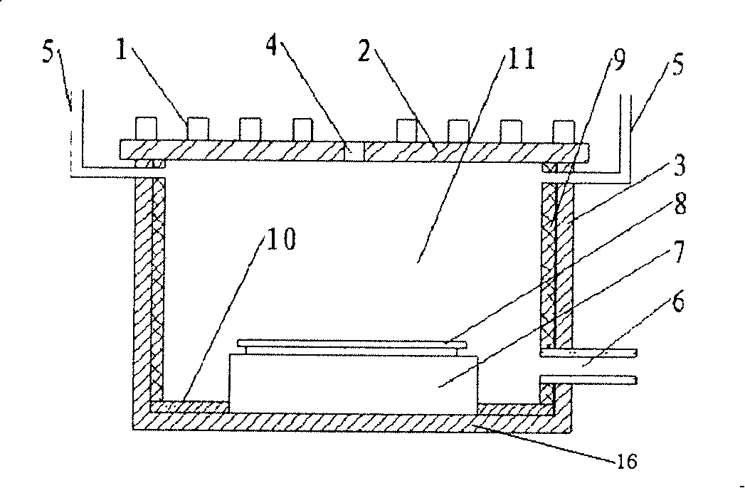
[0035] The reaction chamber lining of the present invention is mainly used to protect the wall of the reaction chamber. The reaction chamber mentioned here mainly refers to the reaction chamber of the semiconductor wafer processing equipment, and may also be other chambers.

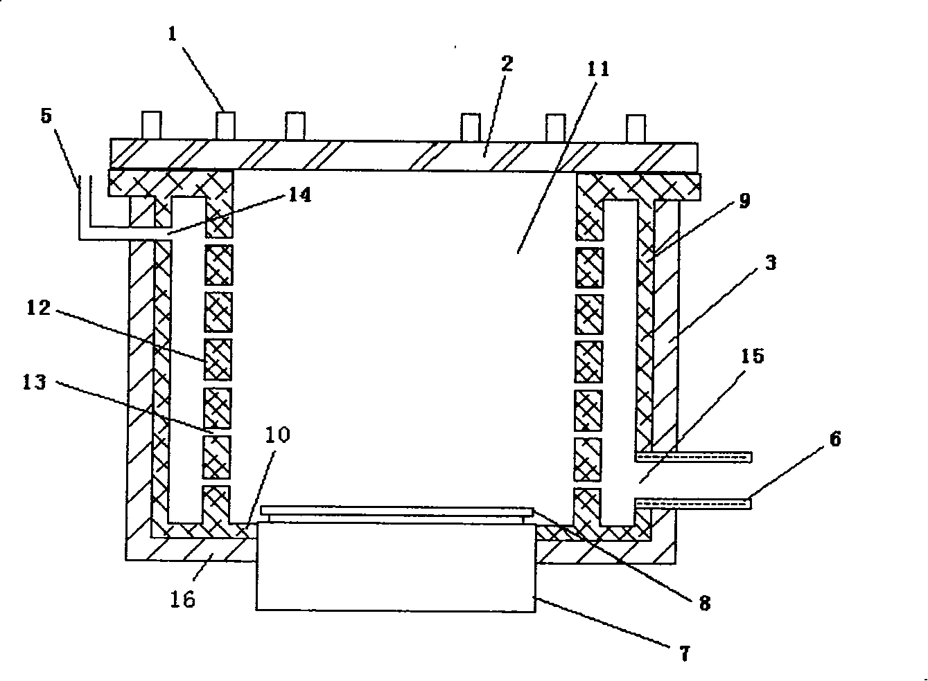
[0036] Its preferred specific implementation is as figure 2 , image 3 Shown, comprise side liner and bottom surface liner 10, wherein side liner is divided into two layers, are inner layer inner liner 12 and outer layer inner liner 9 respectively, the upper edge of inner layer inner liner 12 and outer layer inner liner 9 mutually Connection; the lower edge is respectively connected with the bottom lining 10, so that a closed space is formed between the inner lining 12 and the outer lining 9.

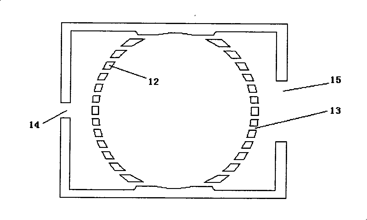
[0037] The inner lining 12 is provided with a plurality of air holes 13 , and the closed space between the inner lining 12 and the outer lining 9 communicates with the reaction chamber 11 through the air holes 13...


PUM


Abstract

The invention discloses a reaction cavity lining and a reaction cavity containing the lining. The invention comprises a side face lining and a bottom face lining. The side face lining is divided into an inner lining and an outer lining and a sealed space is formed between the two linings. A plurality of pores are cut on the inner lining, and a lining gas intake and a lining gas vent are cut on the outer lining and respectively correspond to the gas intake and the gas vent of the reaction cavity. The process gas first enters the sealed space between the inner lining and the outer lining, and then enters the reaction cavity through the pores of the inner lining. Then the gas enters the sealed space between the inner lining and the outer lining through the reaction cavity and is emitted through the gas vent. The speed of the gas flow in the reaction cavity can be lead to be equalized so as to not only protect cavity walls but also equally distribute the gas in the cavity. The invention is mainly applicable to the reaction cavity of the manufacturing equipment of semiconductors and other similar cavities.

Description

technical field [0001] The invention relates to a semiconductor processing equipment component, in particular to a reaction chamber and its lining. Background technique [0002] Semiconductor wafer processing includes chemical vapor deposition (CVD) of layers of metal, dielectric, and semiconductor materials, such deposition processes including etching of these layers, polishing of photoresist mask layers, and the like. In the case of etching, plasma etching is commonly used to etch metal layers, dielectric layers and semiconductor materials. A parallel-plate plasma reactor generally includes a reaction chamber in which the silicon wafer is etched. After entering the reaction chamber, the etching gas is ionized by electrodes into plasma, and the plasma etches the wafer in the reaction chamber. [0003] During the plasma etch process, the gas is ionized to form a plasma by adding a large amount of energy to the gas at a lower pressure. By adjusting the potential of the wafe...

Claims


Application Information

Patent Timeline
IPC IPC(8): H01L21/00H01L21/3065H01L21/205H01L21/67C23C16/00C23F4/00H01J37/32H05H1/00
Inventor 杨盟
Owner BEIJING NAURA MICROELECTRONICS EQUIP CO LTD
Why Eureka
Try Eureka