Power module and notebook computer

A power module and power conversion circuit technology, which is applied in the direction of circuits, collectors, electrical components, etc., can solve the problems that the power adapter takes up a lot of space, is inconvenient to use, and is disorderly to be retracted and carried.

Inactive Publication Date: 2008-06-25
吕王华
View PDF0 Cites 3 Cited by
  • Summary
  • Abstract
  • Description
  • Claims
  • Application Information

AI Technical Summary

Problems solved by technology

The power cords of the existing power adapters are all connected outside the main part of the adapter. Because the power cords are long, they tend to become disorganized and inconvenient to use when retracting and carrying. The main part of the adapter takes up a lot of space, although now The size of the notebook computer is getting smaller and smaller, and it is very convenient to carry, but its corresponding power adapter has not change

Method used


Image

  • Power module and notebook computer
  • Power module and notebook computer
  • Power module and notebook computer

Examples


Embodiment 1

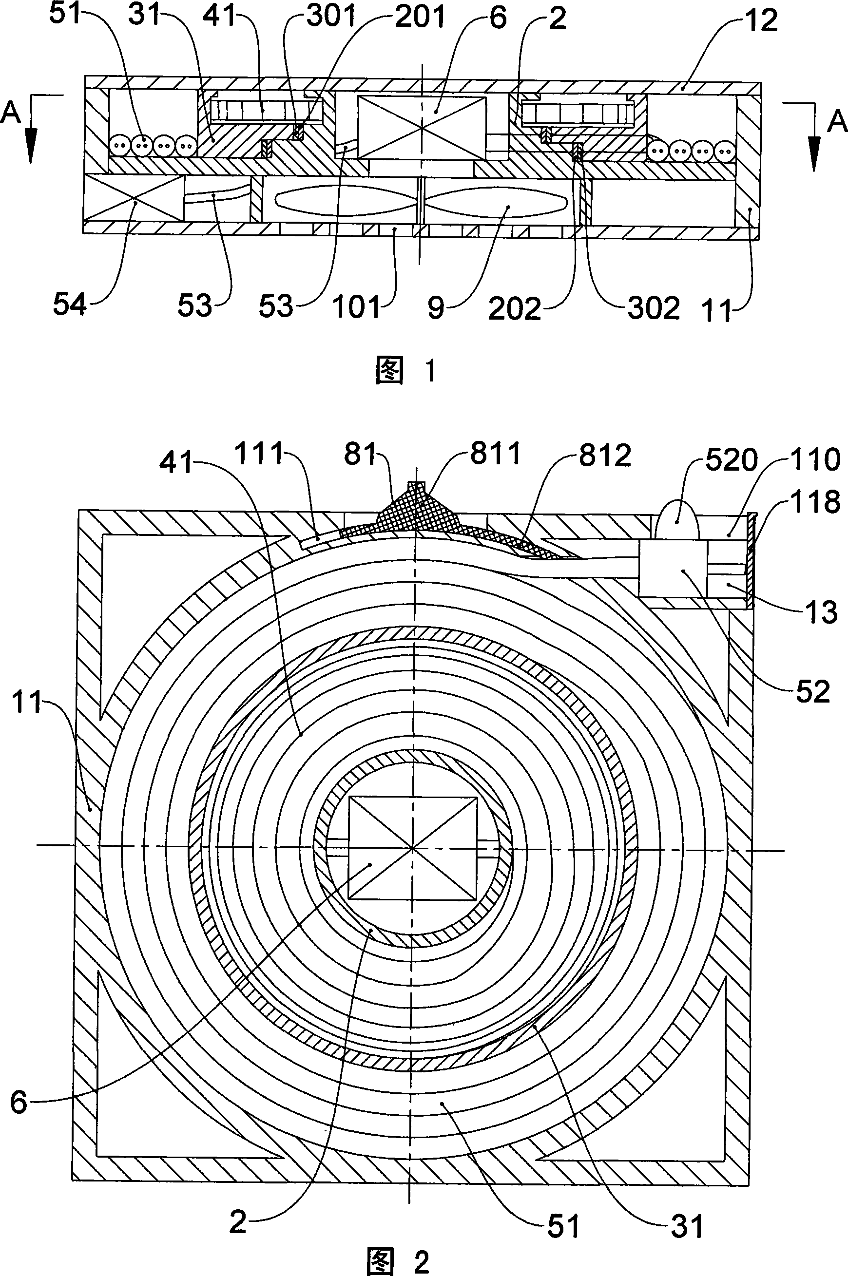
[0041] As shown in Fig. 1, Fig. 2 and Fig. 7, the notebook computer of the present invention includes a display screen, a base 1, and a power module 100, the display screen is connected to the base 1, and the power module 100 is connected to the base 1 For detachable connection.

[0042] The power module 100 includes a housing assembly, a power input wire 51, a power input plug 52, a power output wire 53, a power output interface 54, and a power conversion circuit 6. The housing assembly includes side walls 11, upper and lower covers 12, and The housing assembly is provided with a plug compartment 13, the power input plug 52 is placed in the plug compartment 13, the side of the housing assembly is provided with a chute 110 corresponding to the plug compartment 13, the power supply The input plug 52 is provided with a push block 520, and the push block 520 is adapted and connected with the chute 110, so as to insert the power input plug 52 into the plug compartment 13 or take i...

Embodiment 2

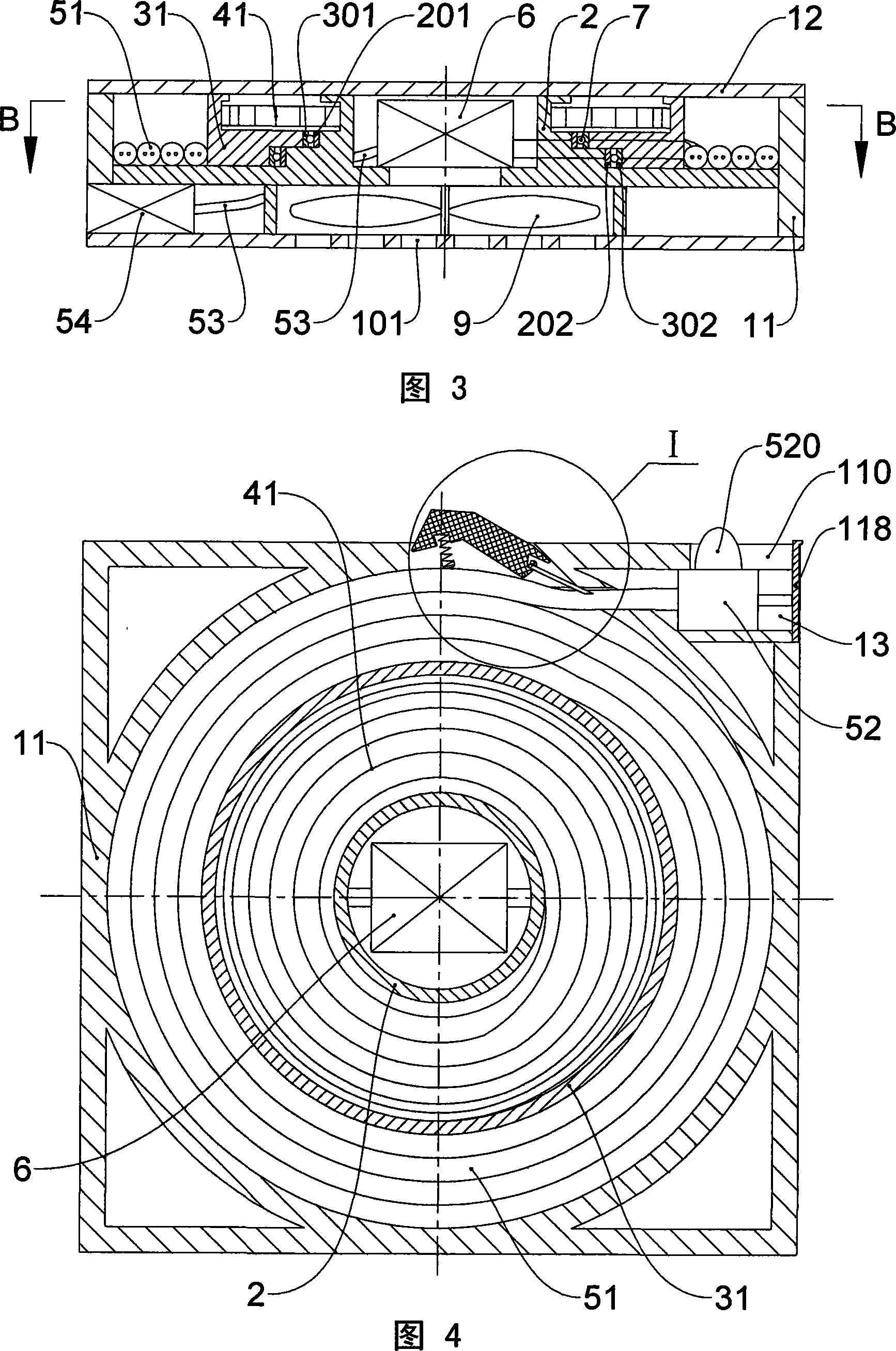
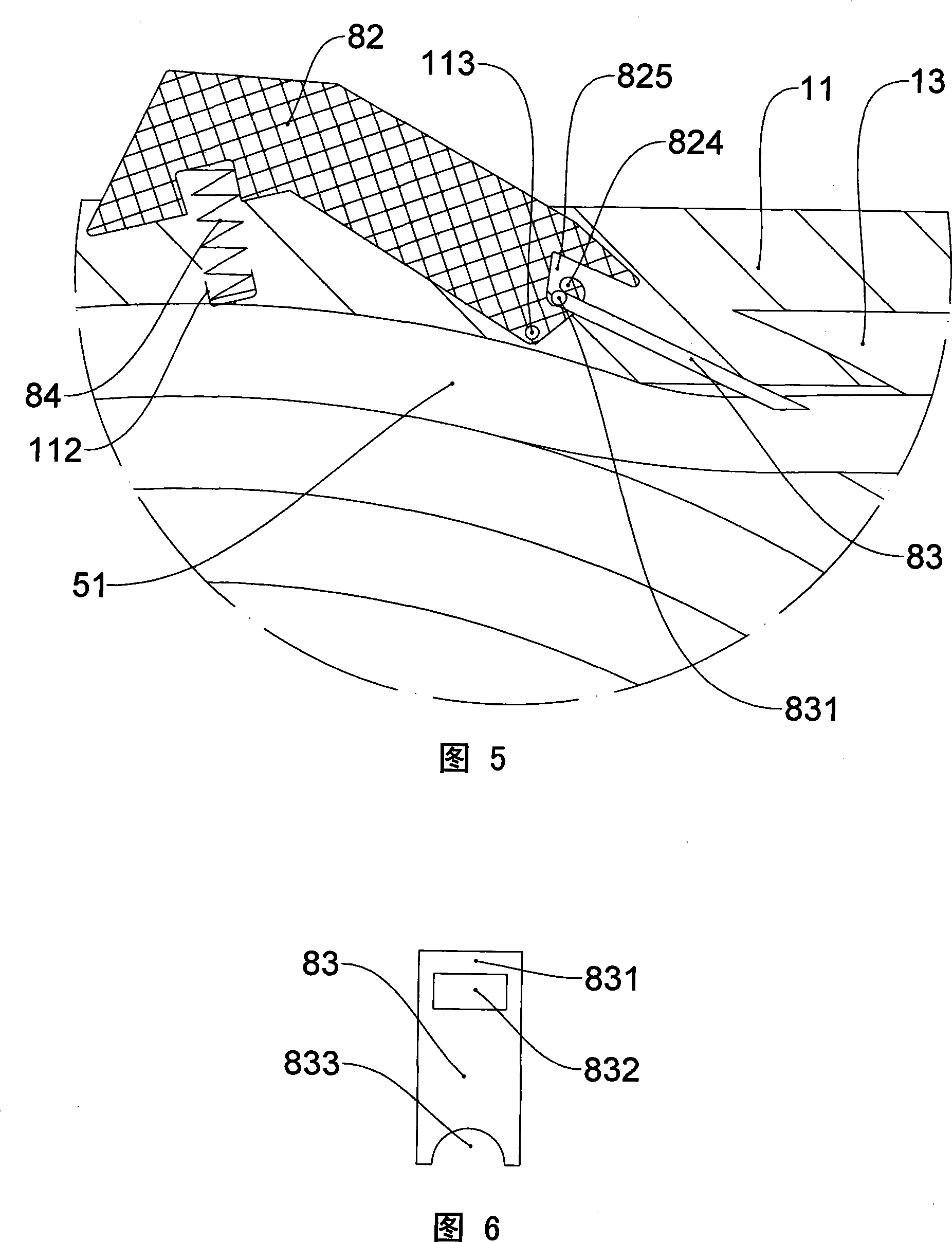
[0047] As shown in Fig. 3, Fig. 4, Fig. 5 and Fig. 6, the difference between this embodiment and Embodiment 1 lies in: the wire locking mechanism and the outer conductive layers 301, 302 and the inner conductive layers 201, 202 The connections between them are different.

[0048] The wire locking mechanism in this embodiment includes a pressing member 82, a pressing member 83, and a compression spring 84. One end of the compression spring 84 is connected to the positioning part 112 on the housing assembly, and the other end is connected to the pressing The head of the pressing member 82 is connected, and the tail of the pressing member 82 is rotatably connected with the fixed shaft 113 located on the housing assembly. The tail of the pressing member 82 is provided with a hook 824 and a guide groove 825. The crimping member 83 is provided with a shaft portion 831, a perforation portion 832, and a crimping portion 833, the hook 824 passes through the perforation portion 832 and ...


PUM


Abstract

The invention discloses a power supply module which has small occupied space, artistic and coordinated outer appearance and convenient collecting and carrying, and a notebook computer which uses the power supply module. The power supply module comprises a casing body component, a power input and output wires (51 and 53), a power output interface (54), a power converting circuit (6) and a wire locking mechanism; wherein ,a hollow jack post (2) is arranged in the casing body component, the jack post (2) adopts a stepped axle, a rotating disk (31) is sleeved on the periphery of the jack post (2), outer conducting layers (301 and 302) are arranged on the surface of the stepped column of the rotating disk (31), inner conducting layers (201 and 202) are arranged on the stepped axle of the jack post (2), the power input wire (51) is connected with the outer conducting layers (301, 302), the input terminal of the power converting circuit (6) is connected with the inner conducting layers (201 and 202), a torsion spring (41) is arranged between the rotating disk (31) and the jack post (2), the power input wire (51) is entwined on the outer circumference of the rotating disk (31), and the power output interface (54) is connected with the output terminal of the power converting circuit (6).

Description

technical field [0001] The invention relates to a power supply module and a notebook computer using the power supply module. Background technique [0002] At present, rechargeable batteries are widely used as a fixed power source on notebook computer products, but the capacity of rechargeable batteries is limited, so that the working hours of notebook computers are relatively short, and the power of the rechargeable batteries will be exhausted after a few hours of general work. In addition, general notebook computers are also equipped with an external power adapter to obtain the rated voltage and current required for normal work. The power cords of the existing power adapters are all connected outside the main part of the adapter. Because the power cords are long, they tend to become disorganized and inconvenient to use when retracting and carrying. The main part of the adapter takes up a lot of space, although now The size of the notebook computer is getting smaller and sm...

Claims


Application Information

Patent Timeline
IPC IPC(8): H02G11/02H01R13/72H01R13/60H01R39/64H02M1/00H05K7/20G06F1/16
Inventor 吕王华
Owner 吕王华
Why Eureka
Try Eureka