Electric heating pipe and manufacturing method thereof

A manufacturing method and technology for electric heating tubes, applied in the direction of the shape of the heating element, can solve the problems of no axial support, the insulating material cannot be made too thin, etc., and achieve the effect of avoiding dust, small pipe diameter, and environmental protection in production

Inactive Publication Date: 2008-06-25
廖伟创
View PDF1 Cites 4 Cited by
  • Summary
  • Abstract
  • Description
  • Claims
  • Application Information

AI Technical Summary

Problems solved by technology

However, in the heating cable described in this technical solution, the heating wire is still independently arranged in the insulating fiber, without a fixed axial support, and the insulating material cannot be made too thin, resulting in the existence of thin-diameter products with this type of structure. certain degree of difficulty

Method used


Image

  • Electric heating pipe and manufacturing method thereof

Examples


Embodiment 1

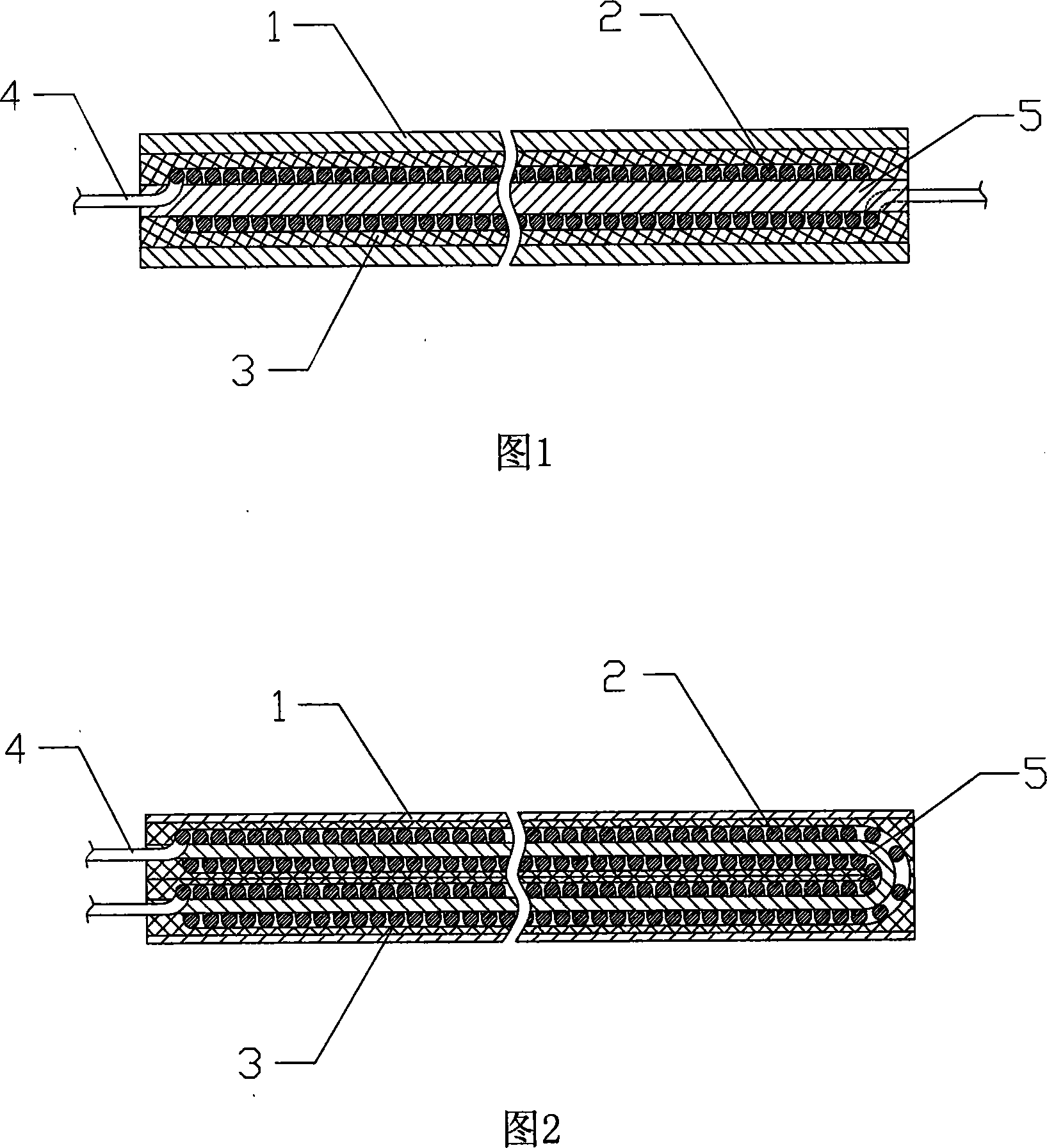
[0033] The electric heating tube has a single-head structure, the heat-resistant fiber core 5 is high silica fiber, the insulating layer 3 is a braided quartz fiber tape, and the rest are conventional electric heating tube preparation materials. The manufacturing method is as follows:

[0034] (a) Winding the heating wire 2 on the heat-resistant fiber core 5, and connecting the electrode lead rods 4 at both ends of the heating wire 2;

[0035] (b) winding the insulating layer 3 outside the heating wire 2;

[0036] (c) Cover the metal shell 1 with the insulating layer 3 to form a semi-finished product;

[0037] (d) Through the flattening process, the above-mentioned semi-finished products are made into finished products of various pipe diameters.

[0038] The electric heating tube that above-mentioned method makes, its pipe diameter φ4.

Embodiment 2

[0040] The electric heating tube has a double-head structure, the heat-resistant fiber core 5 is quartz fiber, the insulating layer 3 is a high-silica fiber braid, and the rest are conventional electric heating tube preparation materials. The manufacturing method is as follows:

[0041] (a) winding the heating wire 2 on the heat-resistant fiber core 5;

[0042] (b) Wrap the insulating layer 3 outside the heating wire 2, and connect the electrode lead rods 4 at both ends of the heating wire 2;

[0043] (c), (d) are the same as embodiment 1.

[0044] The obtained electric heating tube has a pipe diameter of φ2.5.

Embodiment 3

[0046] The electric heating tube has a double-head structure, the heat-resistant fiber core 5 is ceramic fiber, the insulating layer 3 is a mica paper tape, and the rest are conventional electric heating tube preparation materials. The manufacturing method is as follows:

[0047] (a) winding the heating wire 2 on the heat-resistant fiber core 5;

[0048] (b) winding the insulating layer 3 outside the heating wire 2;

[0049] (c) First connect the two ends of the heating wire 2 to the electrode lead rod 4, and then coat the metal shell 1 on the insulating layer 3 to form a semi-finished product;

[0050] (d) Through the tube shrinking process, the above-mentioned semi-finished products are made into finished products with various tube diameters.

[0051] The electric heating tube made by the above method has a pipe diameter of φ3.


PUM


Abstract

The invention relates to an electrothermal pipe, which comprises a metal case and a heat generating wire arranged in the metal case. An insulating layer is arranged between the heat generating wire and the inner wall of the metal case, both ends of the heat generating wire are connected with an electrode leading stick, and the heat generating wire is wrapped on a heat-resistant fiber core. The insulating layer can be an insulating fiber braid, a mica paper braid, a glass cloth or a heat-resistant insulating fiber sleeve pipe. The method for manufacturing the invention mainly comprises the procedures that (a) the heat generating wire is wrapped on the heat-resistant fiber core, (b) the insulating layer is wrapped or sheathed out of the heat generating wire, (c) the metal case is sheath out of the insulating layer for forming a semi-finished product, (d) the semi-finished product is made into a finished product with various pipe diameters by flattening or pipe contracting technology. The invention has the advantages that pipe diameter is petty, the electrothermal pipe with high voltage and low power is conveniently produced, and simultaneously, heat energy utilization of the electrothermal pipe is also enhanced. During the producing preparation process of products, generation of dusts can be greatly reduced or avoided for environmental protection production.

Description

technical field [0001] The invention relates to an electric heating tube and a manufacturing method thereof. Background technique [0002] At present, the basic structure of common electric heating tubes on the market generally includes a metal shell and a heating wire disposed in the metal shell. Both ends of the heating wire are connected with electrode lead rods, which are used to connect to an external power source. An insulating layer is filled between the heating wire and the inner wall of the metal shell. Most of the insulating layers are powder or pre-pressed from powder to form an insulating sleeve. The common powder is magnesium oxide (MgO) powder. And this kind of common electric heating tube is usually prepared by the following manufacturing method: firstly, the electric heating wire is wound into a spiral structure, and then the two ends of the electric heating wire are connected with the motor lead rods, and then the electric heating wire is placed in the metal...

Claims


Application Information

Patent Timeline
Patent Type & Authority Applications(China)
IPC IPC(8): H05B3/44
Inventor 廖伟创
Owner 廖伟创
Why Eureka
Try Eureka