Laser cutting equipment

A laser cutting and equipment technology, applied in laser welding equipment, welding equipment, stone processing equipment, etc., can solve problems such as cracking of glass substrates

Inactive Publication Date: 2008-07-02
FOXSEMICON INTEGRATED TECHNOLOGY (SHANGHAI) INC +1
View PDF0 Cites 14 Cited by
  • Summary
  • Abstract
  • Description
  • Claims
  • Application Information

AI Technical Summary

Problems solved by technology

The glass substrate will have a stress change due to the sharp temperature difference, and the stress change will cause a crack to grow downward at the position of the pre-cut line formed by the cutter wheel on the surface of the glas

Method used


Image

  • Laser cutting equipment
  • Laser cutting equipment

Examples


Example Embodiment

[0010] The embodiments of the present invention will be further described in detail below in conjunction with the accompanying drawings.
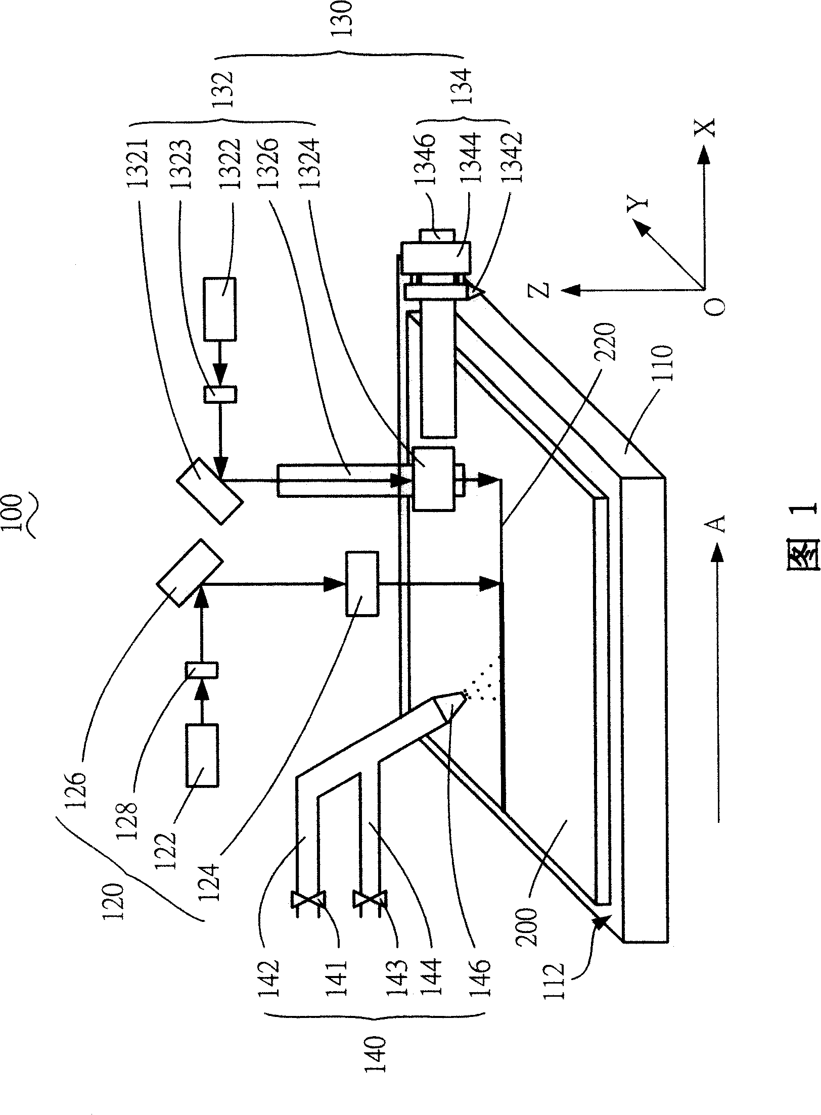
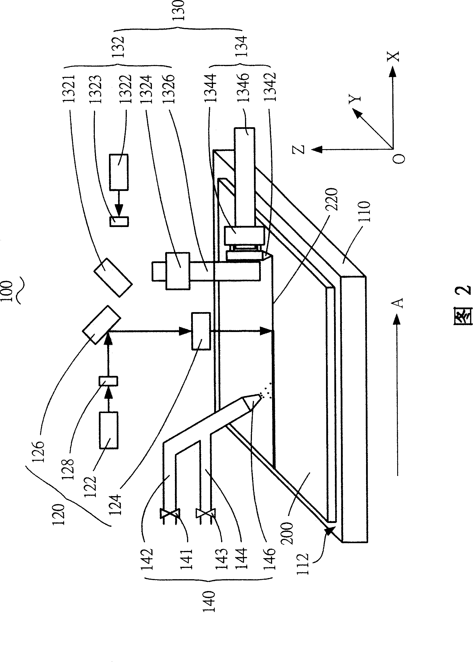
[0011] Please refer to FIG. 1, the laser cutting device 100 provided by the embodiment of the present invention includes a carrying device 110, a laser cutting device 120, a pre-cutting device 130, and a cooling device 140.

[0012] The carrying device 110 has a carrying surface 112 for carrying the brittle material substrate 200 to be cut. The material of the brittle material substrate 200 can be a brittle material such as ceramic, glass, or quartz. Generally, the carrying device 110 can move along the Z-axis direction perpendicular to the carrying surface 112 thereof, and can also move and / or rotate in an X-Y plane parallel to the carrying surface 112.

[0013] The laser cutting device 120 is disposed opposite to the carrying device 110 and is located on the side of the carrying surface 112 of the carrying device 110. The laser cutting device...


PUM


Abstract

The invention provides a laser cutting equipment, comprising a bearing device with a bearing surface, a laser cutting device which is arranged corresponding to the bearing device and at one side of the bearing surface of the bearing device, and a pre-cutting device and a cooling device which are respectively arranged at two corresponding sides of the laser cutting device; wherein, the pre-cutting device comprises a plurality of pre-cutting units which can be switched for usage. The pre-cutting device of the laser cutting equipment can execute various laser cutting processes by shifting different pre-cutting units, thus meeting the cutting requirement of brittle baseplate with different thicknesses and materials.

Description

technical field [0001] The invention relates to a laser cutting device, in particular to a laser cutting device which can be used for cutting brittle material substrates. Background technique [0002] With the continuous development of display technology, thin film transistor liquid crystal display (Thin Film Transistor Liquid Crystal Display, TFT-LCD) and other liquid crystal display devices have been widely used in the consumer field, which is expected to replace the traditional cathode ray tube (Cathode Ray Tube, CRT) display device . Liquid crystal display devices such as TFT-LCD are usually composed of two upper and lower glass plates, a liquid crystal and a number of circuits accommodated between the two glass plates. The liquid crystal can change its arrangement under the action of an electric field to realize the display function of TFT-LCD. In order to form liquid crystal display panels of different sizes, it is usually necessary to cut larger-sized glass substrat...

Claims


Application Information

Patent Timeline
IPC IPC(8): B23K26/42B23K26/04B23K26/08B23K26/14B23K26/40C03B33/02B28D1/32B23K26/402B23K26/70
Inventor 傅承祖黄俊凯何仁钦许宗富方瑞文郭访璇
Owner FOXSEMICON INTEGRATED TECHNOLOGY (SHANGHAI) INC
Why Eureka
Try Eureka