
Natural gas engine electromagnetic valve jet drive circuit

A driving circuit and engine technology, which is applied in the direction of engine components, engine control, combustion engine, etc., can solve problems such as inability to effectively prevent misinjection, impossibility to improve accuracy, and heavy software workload, and achieve simplified injection drive control methods and high reliability. Improved, highly configurable effects

Inactive Publication Date: 2008-07-09
TSINGHUA UNIV
View PDF0 Cites 10 Cited by
  • Summary
  • Abstract
  • Description
  • Claims
  • Application Information

AI Technical Summary

Problems solved by technology

Although the driving circuit is simple to implement, there are some disadvantages: First, the control of the driving current requires software feedback, that is, the single-chip microcomputer samples the driving current, and then modulates and controls the duty cycle of the control pulse. The frequency is low and the accuracy cannot be improved
Secondly, the hardware driver cannot effectively prevent the occurrence of false injection

Method used


Image

  • Natural gas engine electromagnetic valve jet drive circuit
  • Natural gas engine electromagnetic valve jet drive circuit

Examples


Embodiment Construction

[0017] Below in conjunction with embodiment and accompanying drawing, further illustrate the present invention.

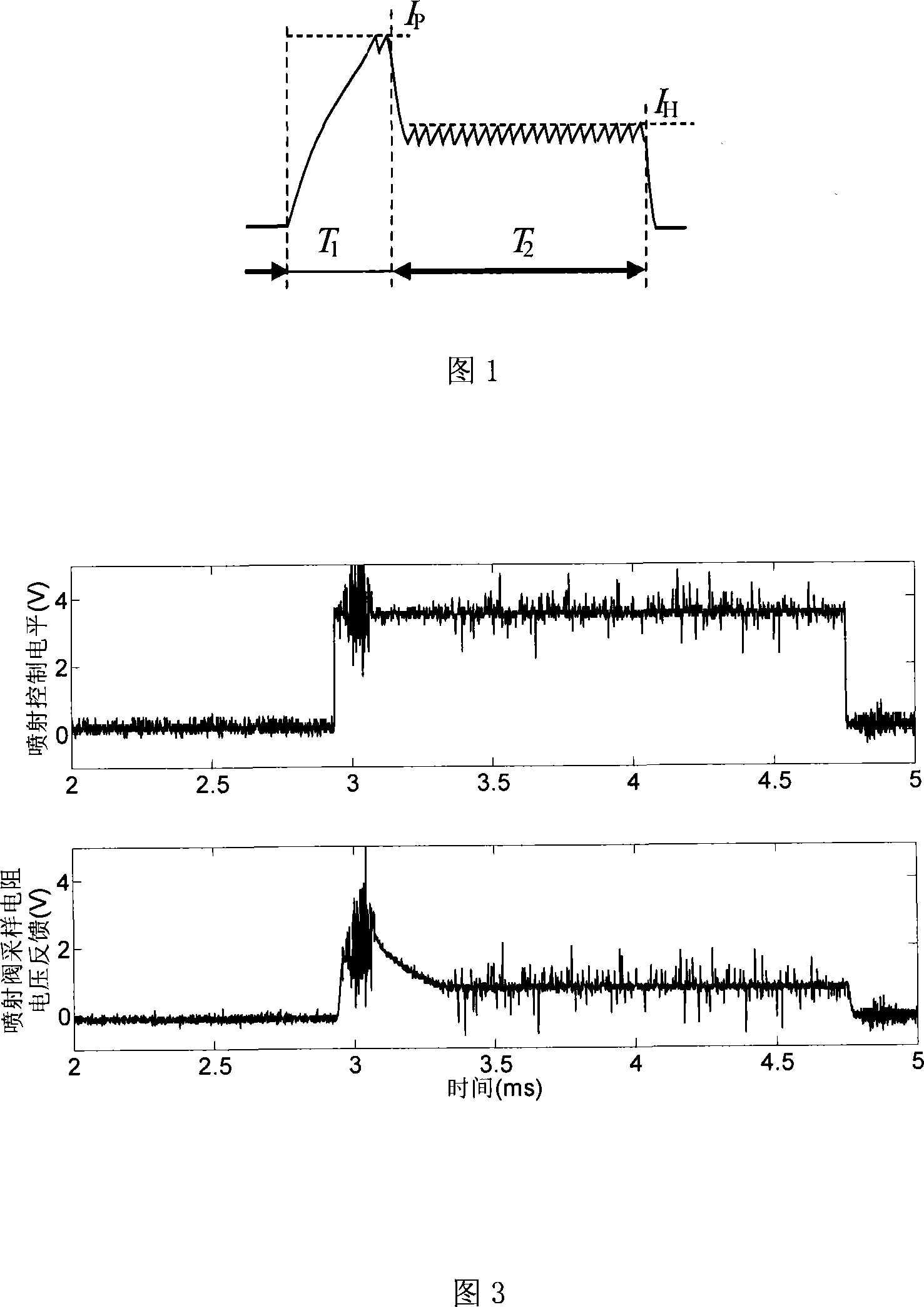
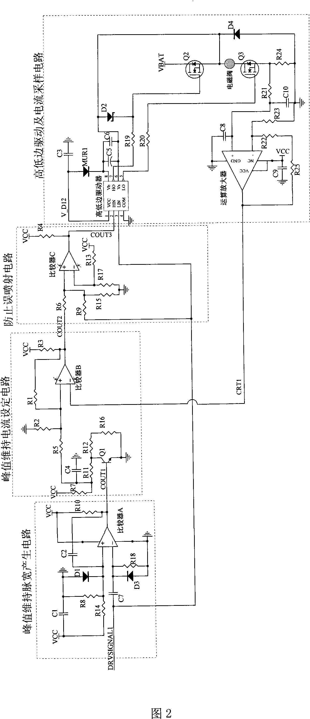
[0018] Figure 1 is a schematic diagram of the driving current. Fig. 2 is a schematic diagram of the present invention. Fig. 3 is a partial signal diagram of the working process of the present invention.

[0019] The whole drive circuit consists of four parts: peak sustain pulse width generation circuit, peak sustain current setting circuit, false injection prevention circuit, high and low side drive and current sampling circuit. The peak sustain pulse width generating circuit is composed of a comparator A and two RC circuits. The injection drive pulse signal is input to one RC circuit, and then input to the negative port of comparator A of LM2902. When the pulse input terminal is at low level, the level at the positive terminal of comparator A is higher than that at the negative terminal, then comparator A outputs low level. After the pulse input terminal become...


PUM


Abstract

The invention provides an electromagnetic valve jet drive circuit for a natural gas engine, and belongs to the technical field of an electric control engine hardware system. The drive circuit comprises a peak value maintenance pulse width generation circuit, a peak value maintenance current setting circuit, a mis-jet preventing circuit, etc. A capacitor C7 is connected with the negative terminal of a jet incoming signal DRVSIGNAL1 and a comparator A. The output signal COUT1 of the comparator A is connected with the base of a triode Q1. A resistor R1 is connected with the anode port the output port of a comparator B. One end of a resistor R9 is connected with a jet control signal DRVSIGNAL1, and the other end is connected with the anode port of a comparator C. The port 2 of a high and low side driver is connected with the output port signal of the comparator C; and a port 8 is connected with the cathode of a diode MUR1. The drain electrode of a MOSFET chip Q2 is connected with a power supply VBAT. The invention generates peak current pulse width, and simplifies the jet drive control mode with high configurability of the circuits. In addition, the invention can effectively prevent mis-jet from occurring.

Description

technical field [0001] The utility model relates to a driving circuit for a solenoid valve injection of a natural gas engine, which relates to a driving circuit for an electronically controlled jet solenoid valve of a natural gas engine, and belongs to the technical field of electronically controlled engine hardware systems. Background technique [0002] In the electronically controlled natural gas engine injection system, the driving control of the solenoid valve is the basis for realizing the precise control of multi-point injection. The action of the solenoid valve is realized by controlling the electromagnetic force generated by the driving current. When the solenoid valve is closed, the drive circuit is connected and an appropriate drive current is generated, and the drive current generates enough electromagnetic force through the solenoid valve coil to drive the armature to move and seat, thereby disconnecting a certain natural gas pipeline of the solenoid valve; when ...

Claims


Application Information

Patent Timeline
Patent Type & Authority Applications(China)
IPC IPC(8): F02D41/26F02M21/02
CPCY02T10/30
Inventor 章健勇李建秋洪木南陈林欧阳明高
Owner TSINGHUA UNIV
Learn More