Straight-through type non-contact hermetic sealing structural design for grease lubricating bearing

A structural design, non-contact technology, applied in the field of bearing sealing, can solve problems such as increased management and production costs, uncertain life of spindle bearings, speed limit at the contact surface, etc., to achieve convenient processing, convenient installation and debugging, minimum pressure requirements Reduced effect

Inactive Publication Date: 2008-07-09
LUOYANG BEARING RES INST CO LTD
View PDF0 Cites 9 Cited by
  • Summary
  • Abstract
  • Description
  • Claims
  • Application Information

AI Technical Summary

Problems solved by technology

[0003] 1. In the labyrinth gap seal structure, due to the existence of the seal gap, for the working environment where there is a large amount of coolant and water vapor or the working end is raised, water and granular impurities formed by processing often enter the inside of the bearing and the main shaft, resulting in Bearing grease fails or even burns the spindle motor installed inside; another problem is that the parts forming the sealing structure have strict requirements on dimensional accuracy and shape accuracy, and strict processing requirements, often need to be repaired, which increases management and production costs
[0004] 2. The contact cup seal can form a tight protection to avoid the entry of external pollutants, but the disadvantages are obvious, mainly the linear speed at the contact surface is strictly limited and the working life is low and unstable, which in turn causes the life of the spindle bearing to be short. Sure
[0005] 3. The main problem of the air seal is that the air is discharged from a single point of inclination, the seal is uneven, and there are also hidden dangers in the work

Method used


Image

  • Straight-through type non-contact hermetic sealing structural design for grease lubricating bearing

Examples


Embodiment Construction

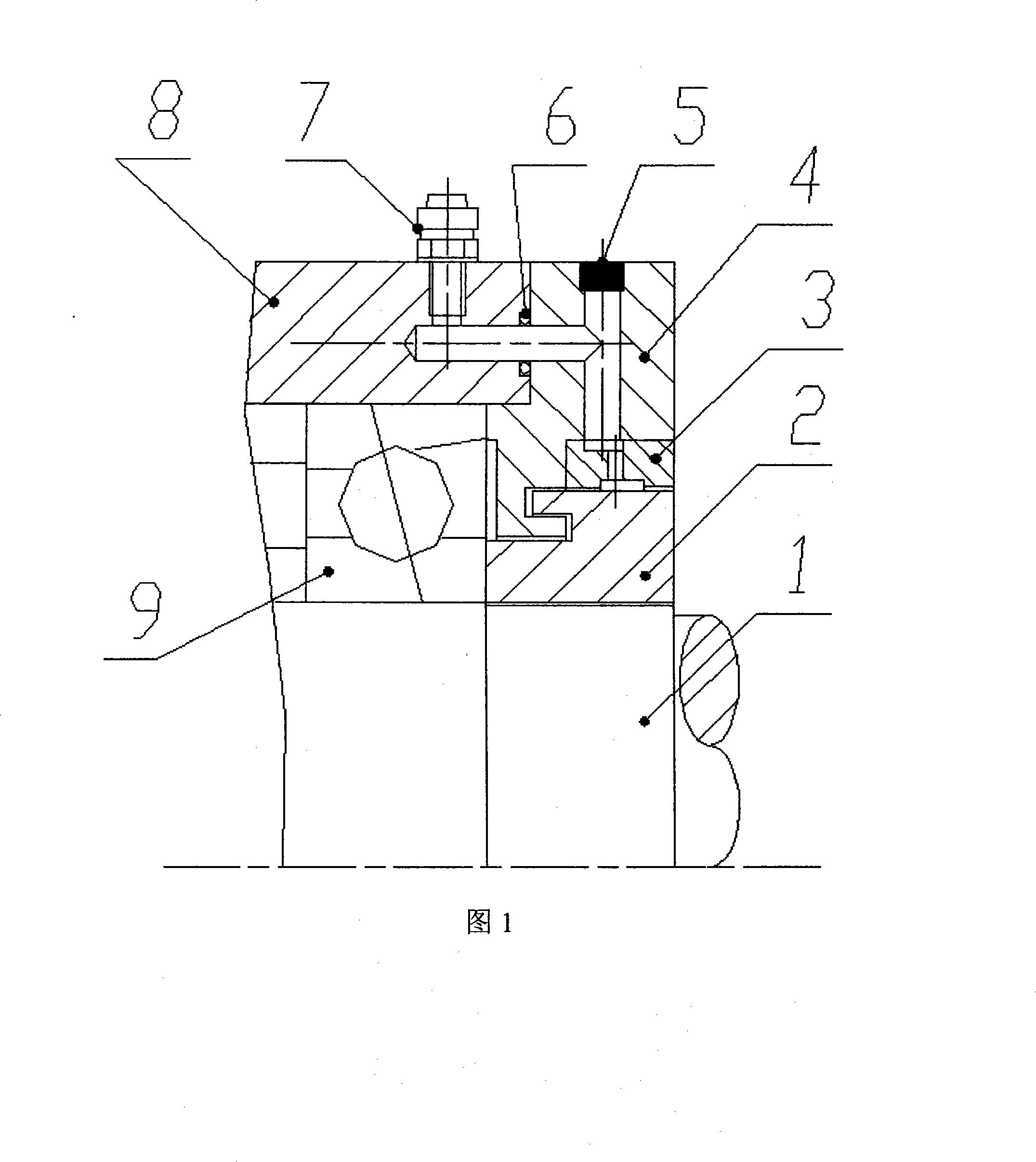
[0018] As shown in Figure 1: the front cover (4) is an assembly, the gas distribution ring (3) and the front cover (4) adopt interference fit, and are assembled together by press-fitting. Straight air hole outer end is blocked with plug (5). The front cover (4) and the housing (8) are reliably connected with bolts. During installation, it must be ensured that the horizontal air holes of the housing (8) and the front cover (4) are aligned and communicated, and the O-ring (6) is tightly leak-proof.

[0019] During work, the compressed air enters the horizontal air passage of the housing (8) of the rotating shaft (1) through the air intake nozzle (7) fixed on the housing (8), and then enters the horizontal air passage and vertical air passage of the front cover (4). into the air cavity formed by the front cover (4) and the outer diameter ring groove of the gas distribution ring (3), the compressed air is gathered and evenly distributed, and then sprayed out at high speed through ...


PUM


Abstract

A through-type non-contact hermetic structure used on a grease-lubricated bearing is provided. A horizontal gas path and a vertical gas path communicated with the horizontal gas path are processed on the front cover (4) of a fixed bearing (9). The horizontal gas path is communicated with the gas path of a shell (8) and provided with an inlet gas nozzle (7), and is sealed by an O-shaped seal ring (6). The shell is fixed by a bolt to tighten the bearing (9). A stopper (5) is arranged on the external end of the vertical gas path, and the other end thereof is communicated with the gas path of a gas-separating ring (3). The gas-separating ring is provided with staggered ring grooves, and eight small through-holes which are uniformly distributed inside the grooves in the normal direction of the ring grooves and communicated with the inner and the outer ring grooves. The outer ring grooves are matched with the vertical gas path. The inner ring grooves are matched with a fixed screw (2) with a clearance left therebetween. A screw-connected rotating shaft (1) compresses the bearing. The compressed air enters the horizontal gas path and the vertical gas path through the gas nozzle and gathers inside the gas chamber formed by the outer ring grooves of the gas-separating ring, and then is jetted out of the small through-holes into the gas chamber formed between the fixed screw and the gas-separating ring to be uniformly separated to form a pressure ring-shaped zone to avoid the invasion of impurities.

Description

technical field [0001] The invention belongs to the technical field of bearing seals, and in particular relates to a straight-through non-contact air seal structure design used on grease lubricated bearings. Background technique [0002] At present, the lubrication of electric spindles to the bearings is mostly lubricated with grease. In order to protect the entry of external pollutants, this lubrication method mostly adopts labyrinth gap seals, contact cup seals or air seals at the front end of the bearings. These three sealing methods: [0003] 1. In the labyrinth gap seal structure, due to the existence of the seal gap, for the working environment where there is a large amount of coolant and water vapor or the working end is raised, water and granular impurities formed by processing often enter the inside of the bearing and the main shaft, resulting in Bearing grease fails or even burns the spindle motor installed inside; another problem is that the parts forming the sea...

Claims


Application Information

Patent Timeline
Patent Type & Authority Applications(China)
IPC IPC(8): F16J15/40
Inventor 田民邱宪国陈长江李严李娟
Owner LUOYANG BEARING RES INST CO LTD
Why Eureka
Try Eureka