Combined light guide board and preparation method

A manufacturing method and technology for a light guide plate, which are applied in chemical instruments and methods, light guides, optics, etc., can solve the problems of production efficiency limitation, product price increase, and difficulty in mold manufacturing, and achieve precise structure, stable quality, and stable quality. control effect

Inactive Publication Date: 2008-07-09
陈林森
View PDF0 Cites 33 Cited by
  • Summary
  • Abstract
  • Description
  • Claims
  • Application Information

AI Technical Summary

Problems solved by technology

The accuracy of dots produced by this method is higher than that of screen printing. However, when manufacturing large-size light guide plates, it is extremely difficult to manufacture molds, which increases the price of the product.
At the same time, the common point of the above-mentioned methods is that dots are made on a sheet substrate of a certain size, and the production efficiency is limited.

Method used


Image

  • Combined light guide board and preparation method
  • Combined light guide board and preparation method

Examples


Embodiment 1

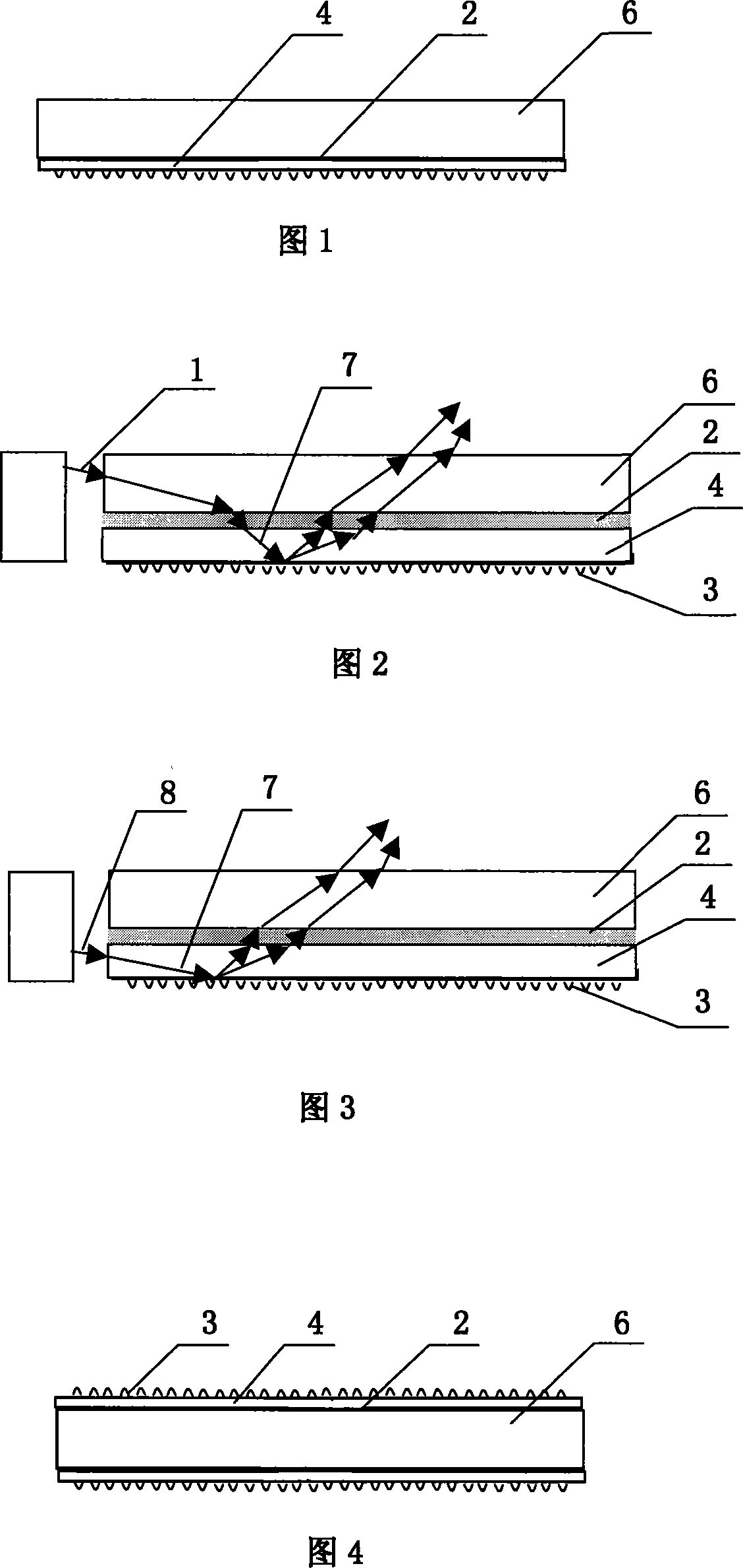
[0033] Embodiment 1: Referring to Fig. 1 to Fig. 3, Fig. 1 is a schematic diagram of a double-layer composite structure, wherein 6 is a PC board, 2 is a viscous composite material (light-curing resin), and 4 is a flexible light-guiding film after cutting. Its light guide principle is similar to the current general single-sided dot light guide plate.

[0034] The specific manufacturing process includes the following steps:

[0035] (1) making a metal mold for the production of the flexible light guide film 4;

[0036] (2) Fabricate flexible light-guiding film 4 by roll-to-roll micro-nano imprinting method;

[0037] (3) Coating the viscous substance cured resin on the non-dot surface of the flexible light guide film 4 by a roll-to-roll coating method;

[0038] (4) Precisely cut the light guide film 4 coated with photocurable resin according to the size of the light guide plate;

[0039] [5] Composite the slit light guide film 4 and the PC board 6 , and provide the process con...

Embodiment 2

[0042] Embodiment 2: Referring to Fig. 4, it is a schematic diagram of a three-layer composite structure, wherein 4 is a light guide film after cutting, 2 is a viscous composite material (high light-transmitting hot-melt adhesive), and 6 is a PMMA plate. The light guide principle of the three-layer structure is similar to the current light guide plate with double-sided dots on the upper and lower surfaces. The specific structure is as follows: two layers of flexible light guiding films 4 are provided, and the two layers of light guiding films 4 are respectively compounded on both sides of the PMMA sheet 6, and the outer surfaces of the two layers of light guiding films 4 are respectively provided with light guiding films. The inner surface of the dot 3 is coated with a high-transmittance hot-melt adhesive, and after heating, the light-guiding film is bonded to the PMMA plate.

Embodiment 3

[0043] Embodiment 3: Refer to FIG. 5 , which is a schematic diagram of making a light guide film by roll-to-roll embossing. The embossing process uses the relative rotation of the driving roller and the driven roller to emboss the microstructured light guide dots on the surface of the mold core to the surface of the flexible PC film. The embossing process is line contact, and the plate roller rotates at a constant speed during the embossing process, so the pressure in the contact surface is very uniform. The roll of PC film is wound on the surface of the plate roll, and the embossing process is not limited by the area. At the same time, the speed of roll-to-roll embossing can reach tens of meters per second, which greatly improves production efficiency.


PUM


Abstract

The invention discloses a composite light guide plate structure and a high-efficiency production method for fabricating the light guide plate structure. The production method is characterized in that a flexible light guide thin film is compounded with a substrate layer, the composite light guide plate includes a double-layer or three-layer structure, and light guide grid dots are distributed on the lower surface or on the upper and the lower surfaces of the composite structure, wherein the flexible light guide thin film is produced by advanced reel-to-reel micro-nano imprint and is compounded with the substrate layer through a transparent viscous substance. The invention can greatly improve the production efficiency, and the grid dots manufactured by reel-to-reel micro-nano imprint have the advantage of high consistency, thus ensuring the performance stability of the light guide plate. The invention is particularly applicable for large-size backlight module and has the advantage of low cost. Meanwhile, the invention belongs to environment-friendly manufacture method due to no organic solve discharge in the screen printing process.

Description

technical field [0001] The invention relates to a liquid crystal backlight module, in particular to a light guide plate structure used in the liquid crystal backlight module, especially suitable for liquid crystal displays and other large-area backlight modules. Background technique [0002] In recent years, liquid crystal displays (LCDs) have become more and more widely used, and a large area has become a development trend thereof. The LCD itself does not emit light, so the backlight module becomes a necessary component to provide its light emission. The main structure of the backlight module is as follows: light source, light guide plate, diffuser, prism sheet, and reflector. Among them, the light guide plate converts CCFL line light source or LED point light source into surface light source, which is the core light guide device in the module. Its manufacturing method and technology directly determine the performance and price of the light guide plate. Researching differ...

Claims


Application Information

Patent Timeline
Patent Type & Authority Applications(China)
IPC IPC(8): G02B6/00G02F1/13357B32B7/02B32B37/12G02F1/1335
Inventor 陈林森周小红
Owner 陈林森
Why Eureka
Try Eureka