Client distribution automation remote real time monitoring system

A distribution network automation and real-time monitoring technology, applied in the direction of electrical program control, comprehensive factory control, comprehensive factory control, etc., can solve problems such as high cost of substation system, potential safety hazards of enterprises and individuals, failure of substation equipment, etc., to ensure data communication and data security, reduce maintenance costs, and prolong service life

Inactive Publication Date: 2008-07-09
毛建良
View PDF0 Cites 62 Cited by
  • Summary
  • Abstract
  • Description
  • Claims
  • Application Information

AI Technical Summary

Problems solved by technology

Most of them are managed in the form of manual on-duty, but operation and maintenance personnel lack practical experience and professional knowledge or have a weak sense of responsibility and other factors, which can easily cause substation equipment failures and accidents occur from time to time, so it is difficult to meet the requirements of enterprise safety, Reliable and economical electricity demand
[0003] On the other hand, the cost of manually maintaining the operation of the enterprise's substation system is relatively high. In order to reduce costs, enterprises often hire some electricians with multiple jobs to manage the enterprise's substations
The actual result of this is often that each enterprise substation managed by the electrician cannot really manage the problem well, which has brought great safety hazards and losses to the enterprise and individuals.
[0004] In addition, the failure of power distribution equipment and personnel misoperation accidents also pose a threat to the safe operation of the power grid.

Method used


Image

  • Client distribution automation remote real time monitoring system
  • Client distribution automation remote real time monitoring system
  • Client distribution automation remote real time monitoring system

Examples


Embodiment Construction

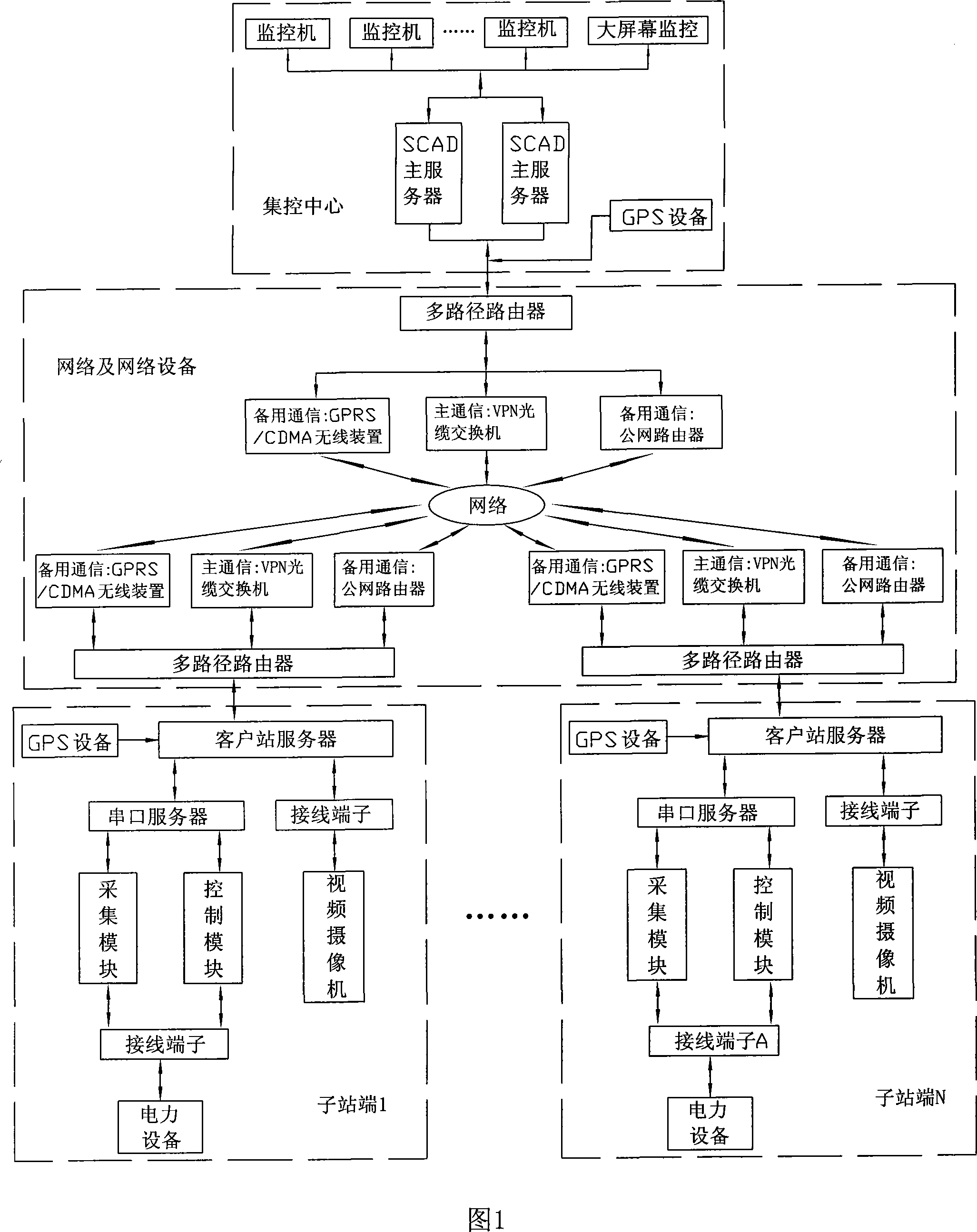
[0029] Comparing with Fig. 1, the system of the present invention is composed of a centralized control center and a plurality of sub-station terminals, and communication between the multiple sub-station terminals and the centralized control center is carried out through respective routers, VPN optical cable switches, optical cables and the main network——VPN professional network Connection, data is transmitted in an externally closed and independent network, and data communication adopts TCP / IP protocol to ensure data communication and data security. At the same time, in order to ensure the reliability of network communication, the communication connection between the central control center and each sub-station can also carry out data communication through backup networks such as GPRS / CDMA wireless communication devices and public networks. The sub-station end and the router of the centralized control center are respectively connected with the client station server and the main ...


PUM


Abstract

The invention relates to a client distribution network automatic remote real-time monitoring system, which conducts remote real-time monitoring on electrical equipments of at least one low-voltage and mid-voltage substation via a main network or a standby network. The system comprises a centralized control center and a plurality of subsite terminals which are communicated with the centralized control center via the network. The system has the advantages of that: a set of automatic management systems are constructed on the subsite terminals, and the centralized control center conducts uniform real-time monitoring on a client substation through the management mode of communicating the network with the centralized control center; thereby ensuring the safe operation of the client substation when unattended, creating an automatic monitoring system, supplying the automatic remote monitoring system of a gap that a prior domestic substation can only be used in a large-scaled substation in the main grid of the power network due to high cost and challenging communication requirements and a common low-voltage and mid-voltage substation is unable to realize automatic remote monitoring due to financial and technical reasons, and establishing the technical basis for major electrical users to achieve socialized professional operation and maintenance.

Description

technical field [0001] The invention relates to a monitoring system of electric equipment, in particular to a real-time remote monitoring system for distribution network automation of medium and low voltage substations. Background technique [0002] With the rapid development of the national economy, the number of large-capacity power users is also increasing rapidly. At present, the operation and maintenance level of the medium and low voltage substation power distribution system equipment set up by these large-capacity users in the enterprise is very weak. Most of them are managed in the form of manual on-duty, but operation and maintenance personnel lack practical experience and professional knowledge or have a weak sense of responsibility and other factors, which can easily cause substation equipment failures and accidents occur from time to time, so it is difficult to meet the requirements of enterprise safety, Reliable and economical electricity demand. [0003] On t...

Claims


Application Information

Patent Timeline
Patent Type & Authority Applications(China)
IPC IPC(8): G05B19/418
CPCY02P90/02
Inventor 毛建良
Owner 毛建良
Why Eureka
Try Eureka