Self-calibration charge pump circuit used for phase-locked loop and its self-calibration feedback loop

A feedback circuit, charge pump technology, applied in the direction of automatic power control, electrical components, etc., can solve the problems of output current mismatch, unstable circuit state, etc., achieve low current mismatch, large output range, and solve the problem of circuit state stable effect

Inactive Publication Date: 2008-07-16
INST OF MICROELECTRONICS CHINESE ACAD OF SCI
View PDF0 Cites 18 Cited by
  • Summary
  • Abstract
  • Description
  • Claims
  • Application Information

AI Technical Summary

Problems solved by technology

[0008] In view of this, an object of the present invention is to provide a self-calibrating charge pump circuit applied to a phase-locked loop to solve the problems of mismatching output current and unstable circuit state when the output voltage of the charge pump circuit varies widely
[0009] Another object of the present invention is to provide a self-calibration feedback circuit in a charge pump circuit to solve the problems of mismatching output current and unstable circuit state when the output voltage of the charge pump circuit varies widely

Method used


Image

  • Self-calibration charge pump circuit used for phase-locked loop and its self-calibration feedback loop
  • Self-calibration charge pump circuit used for phase-locked loop and its self-calibration feedback loop
  • Self-calibration charge pump circuit used for phase-locked loop and its self-calibration feedback loop

Examples


Embodiment Construction

[0033] In order to make the object, technical solution and advantages of the present invention clearer, the present invention will be described in further detail below in conjunction with specific embodiments and with reference to the accompanying drawings.

[0034] The invention adds a reference branch and a bias branch on the basis of the switch current source circuit of the charge pump, together with the feedback amplifier to form a feedback loop, to ensure that the current pumped out and pumped in by the charge pump is completely matched when the output node voltage changes, and the circuit in an absolutely stable state.

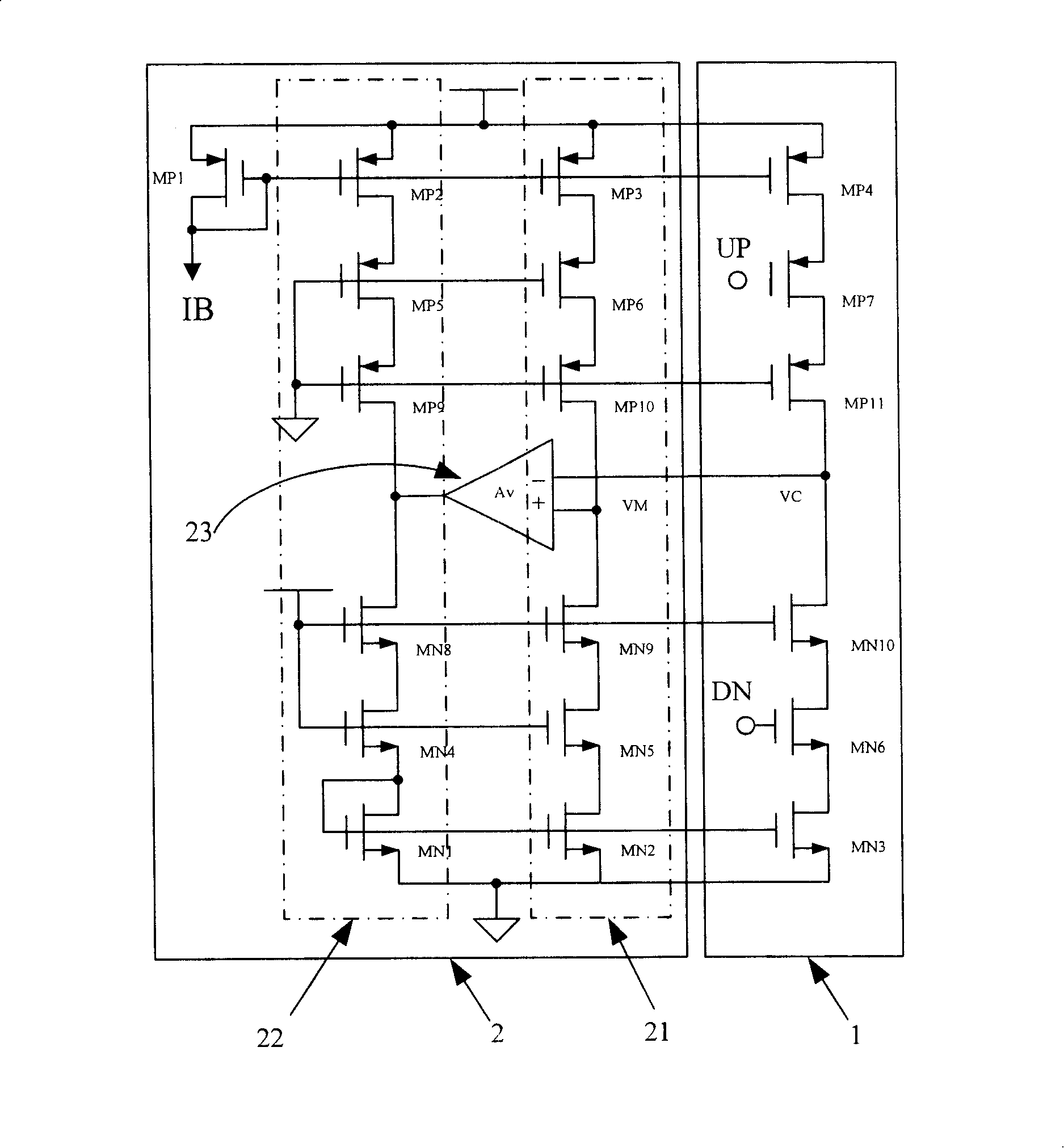
[0035] like figure 1 as shown, figure 1 A circuit diagram of a self-calibration charge pump applied to a phase-locked loop provided by the present invention, the self-calibration charge pump circuit includes a current branch 1 and a self-calibration feedback circuit 2 . The self-calibration feedback circuit 2 includes a reference branch 21 , a bias b...


PUM


Abstract

The invention relating to the phase-locked loop charge pump circuit technical field in microelectronics discloses a self-calibration charge pump circuit used in a phase-locked loop. The invention is characterized in that: the self-calibration charge pump circuit comprises a current branch 1 and a self-calibration feedback circuit 2; the self-calibration feedback circuit 2 comprises a reference branch 21, a biasing branch 22 and a feedback amplifier 23; the reference branch 21 and the output node of the current branch 1 are respectively connected with the positive input end and the negative input end of the feedback amplifier 23; the output end of the feedback amplifier 23 is connected with the biasing branch 22 to from a closed-loop feedback loop. The invention also discloses a self-calibration feedback circuit 2 used in a charge pump circuit. The invention solves the problems of unmatched output current and unstable circuit status of a charge pump circuit when output voltage varies in a large range.

Description

technical field [0001] The invention relates to the technical field of a phase-locked loop charge pump circuit in microelectronics, in particular to a self-calibration charge pump circuit applied to a phase-locked loop and a self-calibration feedback circuit thereof. Background technique [0002] With the rapid development of wireless communication, the RF transceiver front-end of communication equipment has higher and higher performance requirements for the receiver, and the objective requirement is that the loss of the signal-to-noise ratio of the RF front-end is smaller and smaller. In the noise of the radio frequency receiver, in addition to the thermal noise, the phase noise of the phase-locked loop (PLL) is a very important part, and the optimization of the phase noise becomes a key technology in the design of the phase-locked loop. There are many factors that cause the phase noise of the phase-locked loop, including the phase noise of the voltage-controlled oscillator...

Claims


Application Information

Patent Timeline
Patent Type & Authority Applications(China)
IPC IPC(8): H03L7/08H03L7/089
Inventor 杜占坤陈杰
Owner INST OF MICROELECTRONICS CHINESE ACAD OF SCI
Why Eureka
Try Eureka