Gas adsorbing device, vacuum heat insulator making use of gas adsorbing device and process for producing vacuum heat insulator

A gas adsorption, vacuum insulation technology, applied in heat exchange equipment, pipeline protection through thermal insulation, thermal insulation, etc., can solve problems such as difficulty in operation, and achieve the effect of improving yield, maintaining vacuum for a long time, and small deterioration.

Active Publication Date: 2008-07-16
PANASONIC CORP
View PDF1 Cites 11 Cited by
  • Summary
  • Abstract
  • Description
  • Claims
  • Application Information

AI Technical Summary

Problems solved by technology

However, as mentioned above, for more active gas adsorbent materials, its operation becomes more difficult

Method used


Image

  • Gas adsorbing device, vacuum heat insulator making use of gas adsorbing device and process for producing vacuum heat insulator
  • Gas adsorbing device, vacuum heat insulator making use of gas adsorbing device and process for producing vacuum heat insulator
  • Gas adsorbing device, vacuum heat insulator making use of gas adsorbing device and process for producing vacuum heat insulator

Examples


Embodiment approach 1

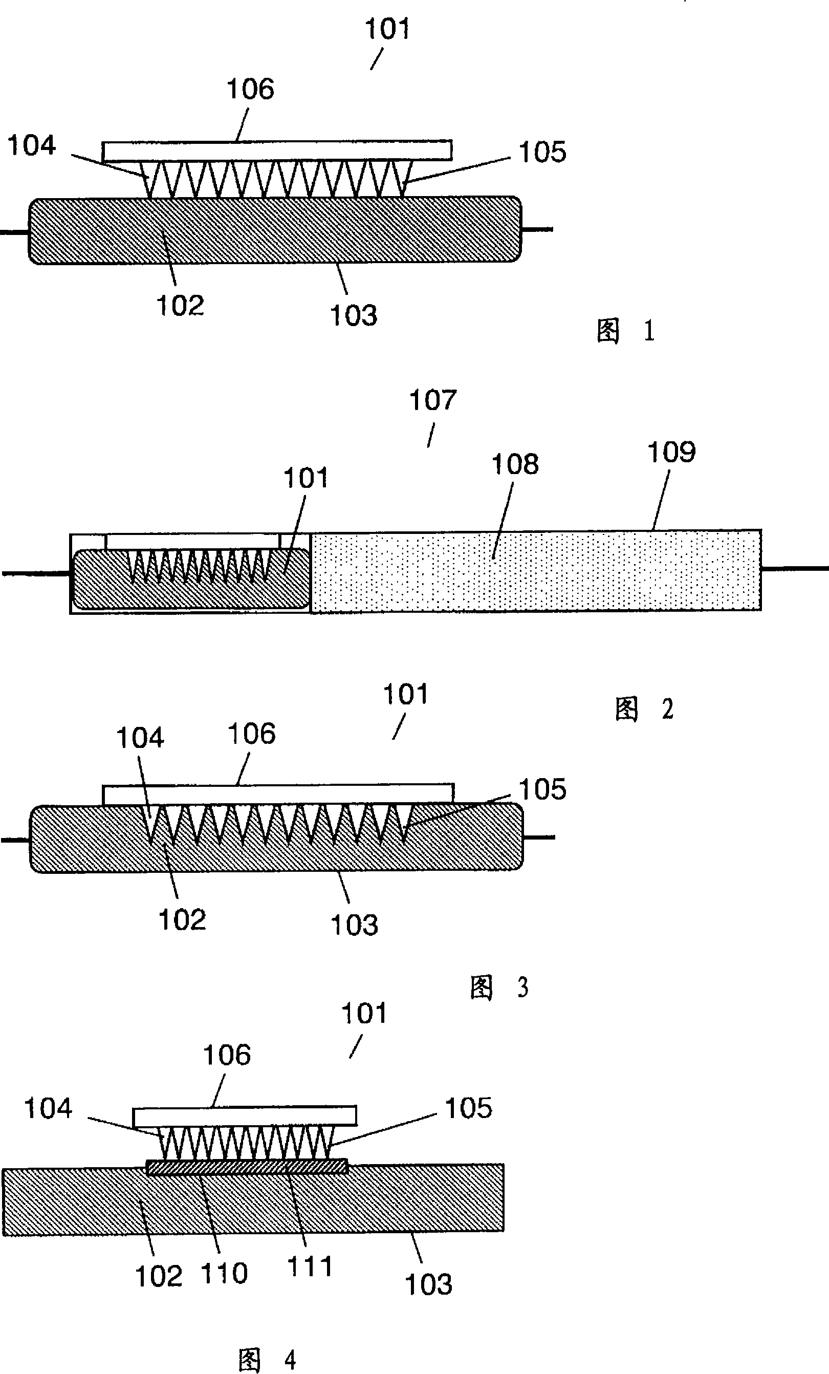
[0110] Fig. 1 is a cross-sectional view of a gas adsorption device according to Embodiment 1 of the present invention.

[0111] In FIG. 1 , a gas adsorption device 101 is equipped with a gas adsorption material 102 inside a container 103 , and a protrusion 104 is in contact with the container 103 . The gas adsorbent 102 is powdered CuZSM-5.

[0112]The container 103 is a bag made by thermally fusing low-density polyethylene, which is a laminated film of low-density polyethylene, aluminum foil, and polyethylene terephthalate, in this order. After 102, it is made by vacuum sealing. The protrusion 104 is in contact with the container 103 by means of the protrusion 105 . The protrusions 104 are fixed on the plate member 106, and the protrusions 105 are arranged in a two-dimensional plane.

[0113] Fig. 2 is a cross-sectional view of the vacuum insulator according to Embodiment 1 of the present invention.

[0114] In FIG. 2 , the vacuum insulator 107 is made by inserting the ga...

Embodiment approach 2

[0124] Fig. 4 is a cross-sectional view of a gas adsorption device 101 according to Embodiment 2 of the present invention.

[0125] In FIG. 4 , a container 103 has an opening 110 , and the opening 110 is covered with a rubber stopper 111 to ensure overall airtightness. The container 103 is made of polyethylene material, and the rubber stopper 111 is made of isobutylene rubber, and the elasticity of the rubber is used to ensure the tightness with the container 103 . In addition, the protrusion 105 of the protrusion 104 is provided so as to be in contact with the rubber stopper 111 .

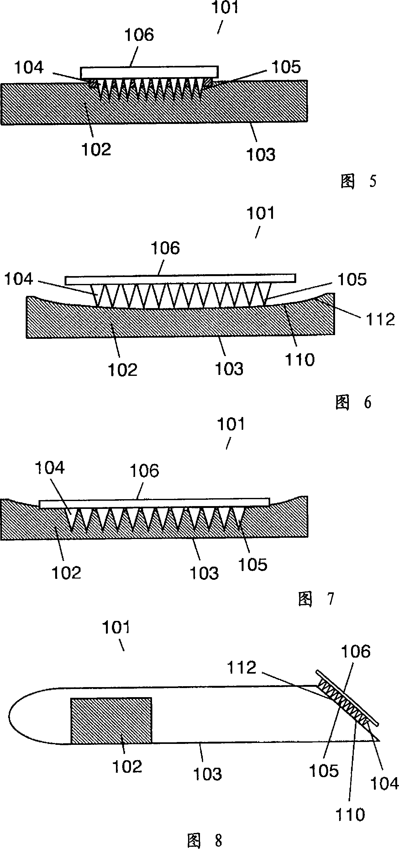
[0126] Fig. 5 is a converted cross-sectional view of the gas adsorption device 101 according to Embodiment 2 of the present invention.

[0127] Next, the operation and function of the gas adsorption device 101 configured as above will be described.

[0128] First, since the gas adsorbent 102 is sealed with a rubber stopper and polyethylene, even if the gas adsorbent 101 is placed in the atmosphe...

Embodiment approach 3

[0132] Fig. 6 is a cross-sectional view of a gas adsorption device 101 according to Embodiment 3 of the present invention.

[0133] In FIG. 6 , a container 103 has an opening 110 , and the opening 110 is covered with a film 112 having gas barrier properties to ensure overall airtightness. The container 103 is made of polyethylene, and the film 112 is a laminated film of low-density polyethylene, aluminum foil, and polyethylene terephthalate in this order, and is bonded by a known method. In addition, the protrusion 105 of the protrusion 104 is provided in contact with the film.

[0134] Fig. 7 is a converted cross-sectional view of the gas adsorption device 101 according to Embodiment 3 of the present invention.

[0135] Next, the operation and function of the gas adsorption device 101 configured as above will be described.

[0136] First, since the gas-adsorbing material 102 is sealed with a gas-barrier film and polyethylene, even if the gas-adsorbing device 101 is placed i...


PUM


Abstract

Casing having a gas adsorbing device and a core material inserted therein is depressurized in a vacuum chamber. Any opening portion thereof is hermetically sealed and air introduction is carried out. In the atmospheric pressure, a pressure of about 1 atm. corresponding to a pressure difference between inside and outside is applied to the casing of vacuum heat insulator. The casing, as consisting of a plastic laminate film, is deformed by pressure, so that stabbing of container with projections occurs to thereby form through holes, resulting in communicating of the gas adsorbent within the container with the interior of the casing. Thus, application to vacuum heat insulator can be realized without any deterioration of gas adsorbent at both of storage and application to vacuum heat insulator, so that long-term retention of vacuum degree can be ensured.

Description

technical field [0001] The present invention relates to a gas adsorbing device having a gas adsorbing material for adsorbing gas by the gas adsorbing material, a vacuum heat insulator having a gas adsorbing device and having vacuum heat insulating performance by adsorbing internal gas by the gas adsorbing device, and manufacture of the vacuum heat insulator method. Background technique [0002] In recent years, expectations for industrial technologies requiring high vacuum are increasing. For example, from the viewpoint of preventing global warming, energy saving is strongly desired, and energy saving is also an urgent problem to be solved for home electric appliances. In particular, thermal insulators having excellent heat insulating performance are required from the viewpoint of effective use of heat for heat preservation and heat protection equipment such as refrigerators, freezers, and automatic vending machines. [0003] As a general heat insulator, fiber materials su...

Claims


Application Information

Patent Timeline
Patent Type & Authority Applications(China)
IPC IPC(8): F16L59/06
Inventor 桥田昌道上门一登汤浅明子
Owner PANASONIC CORP
Why Eureka
Try Eureka