
Electropult of ultrasonic diagnosis equipment

A transmitting device and ultrasonic diagnosis technology, which is applied in sonic diagnosis, infrasonic diagnosis, ultrasonic/sonic/infrasonic diagnosis, etc., can solve problems such as low frame frequency of ultrasonic images, low resolution of ultrasonic image frame rates and complex circuits, etc. Achieve high signal-to-noise ratio, increase resolution, and high frame rate

Inactive Publication Date: 2008-07-23
SHENZHEN LANDWIND IND
View PDF0 Cites 11 Cited by
  • Summary
  • Abstract
  • Description
  • Claims
  • Application Information

AI Technical Summary

Problems solved by technology

[0005] The technical problem to be solved by the present invention is to provide a transmitting device for ultrasonic diagnostic equipment, which overcomes the problem of ultrasonic image frame frequency and ultrasonic image resolution when the ultrasonic diagnostic equipment transmitting device of the prior art transmits unipolar pulses multiple times to form a frame of ultrasonic image. Both are relatively low defects, and when a frame of ultrasonic image is formed by transmitting bipolar pulses multiple times, the frame frequency of the ultrasonic image is low and the circuit is complicated

Method used


Image

  • Electropult of ultrasonic diagnosis equipment
  • Electropult of ultrasonic diagnosis equipment
  • Electropult of ultrasonic diagnosis equipment

Examples


Embodiment Construction

[0020] Below according to accompanying drawing and embodiment the present invention will be described in further detail:

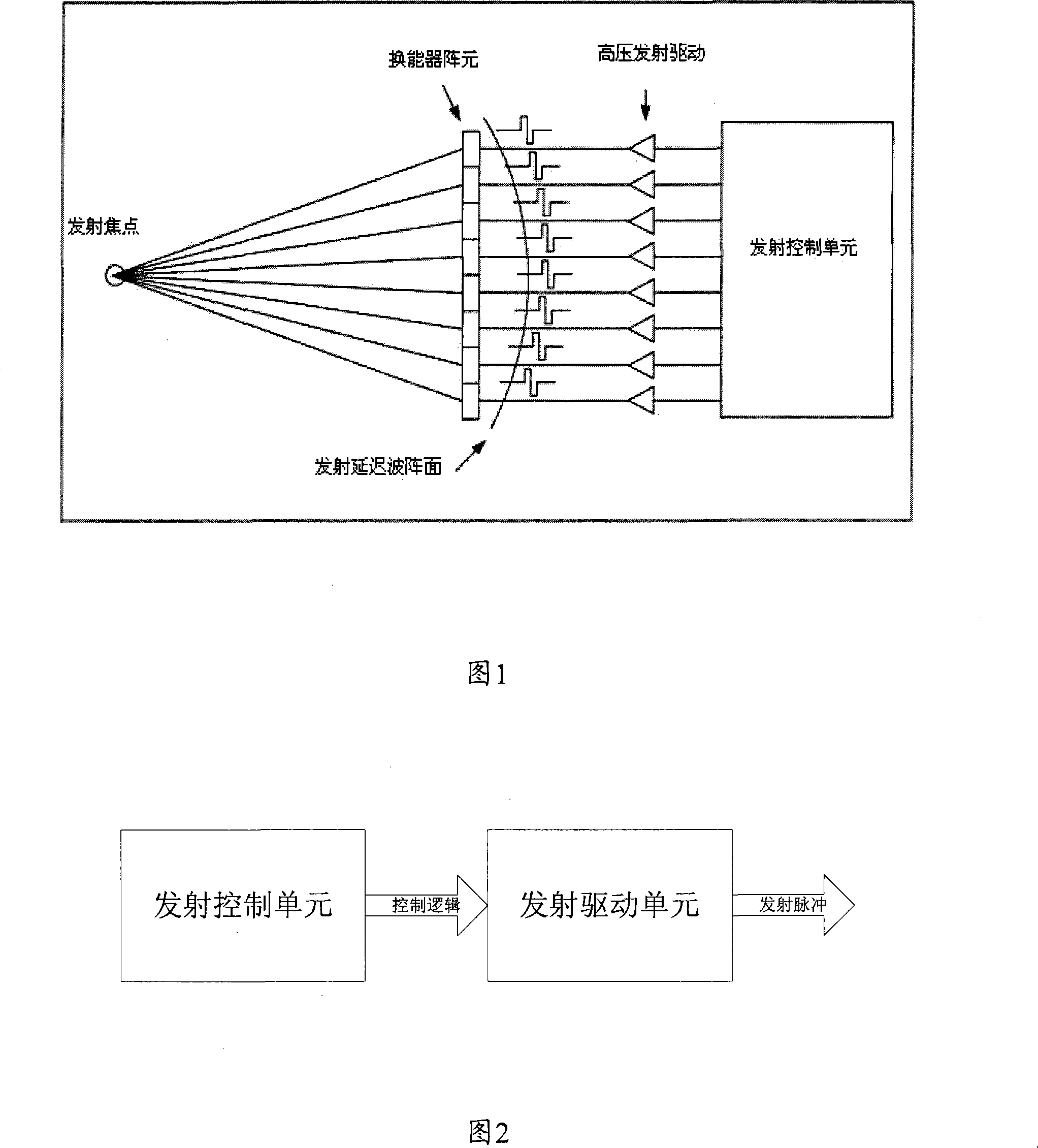
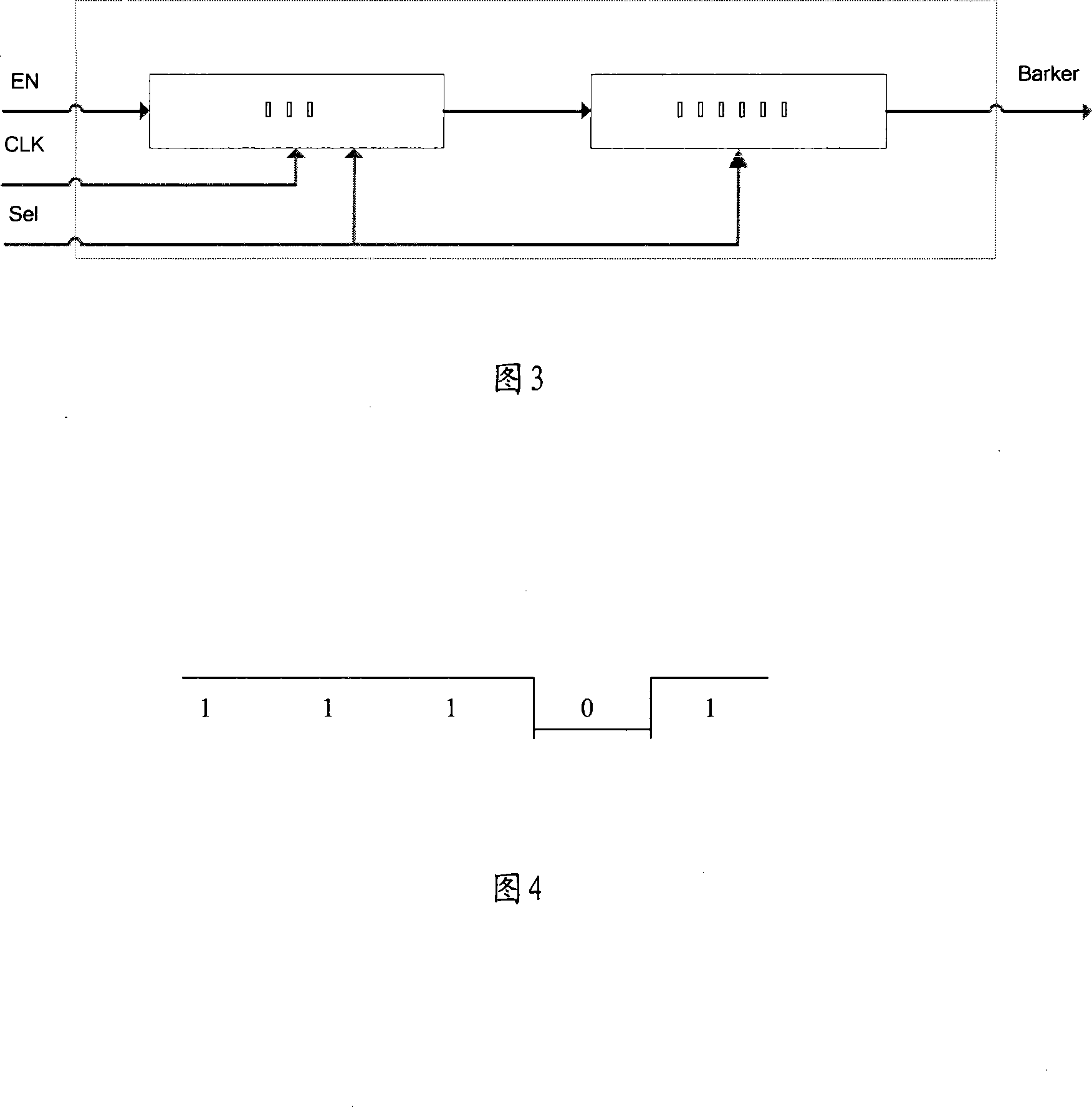
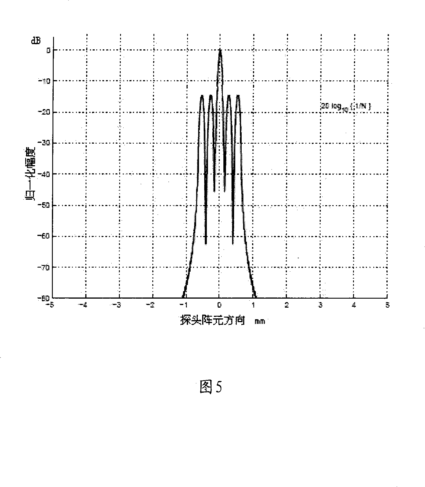
[0021] As shown in Figure 2, the transmitting device of the ultrasonic diagnostic equipment of the present invention includes a transmitting control unit and a transmitting drive unit connected thereto, the transmitting control unit is used to output the Barker code pulse signal, and the transmitting drive unit is used to perform the input of the Barker code pulse signal Amplify and output high voltage Barker code pulse signal. The emission control unit only needs one control signal (high level "1" and low level "0") to control the level output. An N-bit Barker code sequence can be generated by outputting the control signal for N cycles. The emission drive unit adopts unipolar high voltage (H VPP ) and ground potential (0V) as the output level of the emission pulse. The control signal is "1", then output H VPP ; When the control signal is "0", the outp...


PUM


Abstract

The invention discloses a transmitting device of an ultrasonic diagnostic equipment, including a transmitting control unit and a transmitting drive unit which is connected with the transmitting control unit, the transmitting control unit is used for the output of the Barker code pulse signal, the transmitting drive unit is used for amplifying the input Barker code pulse signal and the output of the high-voltage Barker code pulse signal. The transmitting device of the ultrasonic diagnostic equipment of the invention adopts the Barker code rather than the simple pulse as the incentive signal of an ultrasonic sensor, as the Barker code has the nature of an acute autocorrelation function, the higher signal-to-noise ratio is obtained and the resolution of the ultrasound image is improved; at the same time, the invention adopts the single transmission method, which also ensures the high frame rate of the ultrasound image.

Description

technical field [0001] The invention relates to the technical field of ultrasonic diagnostic equipment, in particular to a transmitting device for ultrasonic diagnostic equipment. Background technique [0002] In the ultrasonic diagnostic equipment of the prior art, the emission of ultrasonic waves generally uses high-voltage pulses to excite piezoelectric elements, thereby generating ultrasonic waves of a certain frequency into the human body, and utilizing the discontinuity of the internal acoustic resistance of the human body to pass the reflected sound wave energy through The sensors receive and then pass on to each receive channel of the system respectively. These receiving channels first amplify the signals from the sensors, then digitize them, and then extract two-dimensional tissue information and blood flow Doppler information through a series of processing such as beamforming. [0003] As shown in Figure 1, the electronic focusing of the sound beam is realized by ...

Claims


Application Information

Patent Timeline
IPC IPC(8): A61B8/00B06B1/00
Inventor 刘明宇马勇
Owner SHENZHEN LANDWIND IND
Learn More