Wire cutting electric-discharge machining device of double three-dimension position coordinate system

A three-dimensional position, electrical discharge machining technology, used in electric machining equipment, metal processing equipment, electrode manufacturing, etc., to achieve the effect of low surface roughness

Active Publication Date: 2008-07-23
泰州市海通资产管理有限公司
View PDF0 Cites 9 Cited by
  • Summary
  • Abstract
  • Description
  • Claims
  • Application Information

AI Technical Summary

Problems solved by technology

[0009] The object of the present invention is to provide a double-three-dimensional coordinate line-cut electric discharge machining device, and its purpose is to solve the above-mentioned simultaneous existence of an existing three-dimensional position coordinate line-cut electric discharge machining device in the multiple cutting processes of rough and finish machining. Three aspects

Method used


Image

  • Wire cutting electric-discharge machining device of double three-dimension position coordinate system
  • Wire cutting electric-discharge machining device of double three-dimension position coordinate system
  • Wire cutting electric-discharge machining device of double three-dimension position coordinate system

Examples


Embodiment 1

[0035] Embodiment 1: A double-three-dimensional position coordinate line cutting electric discharge machining device

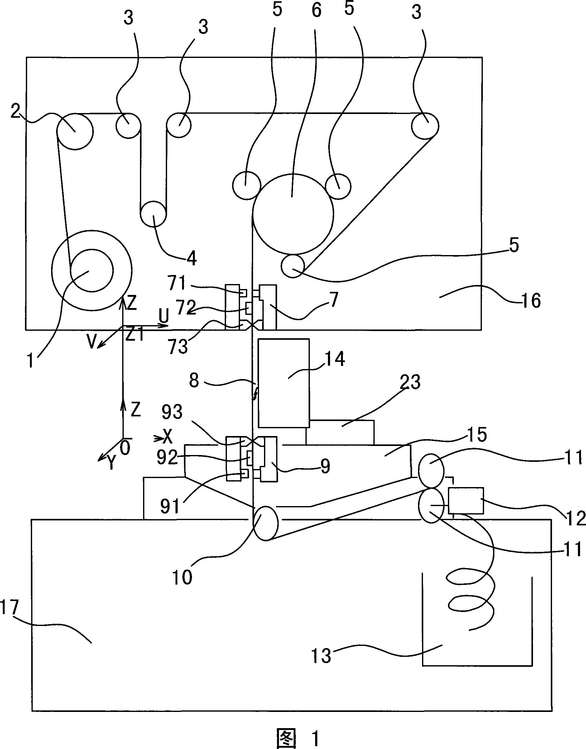
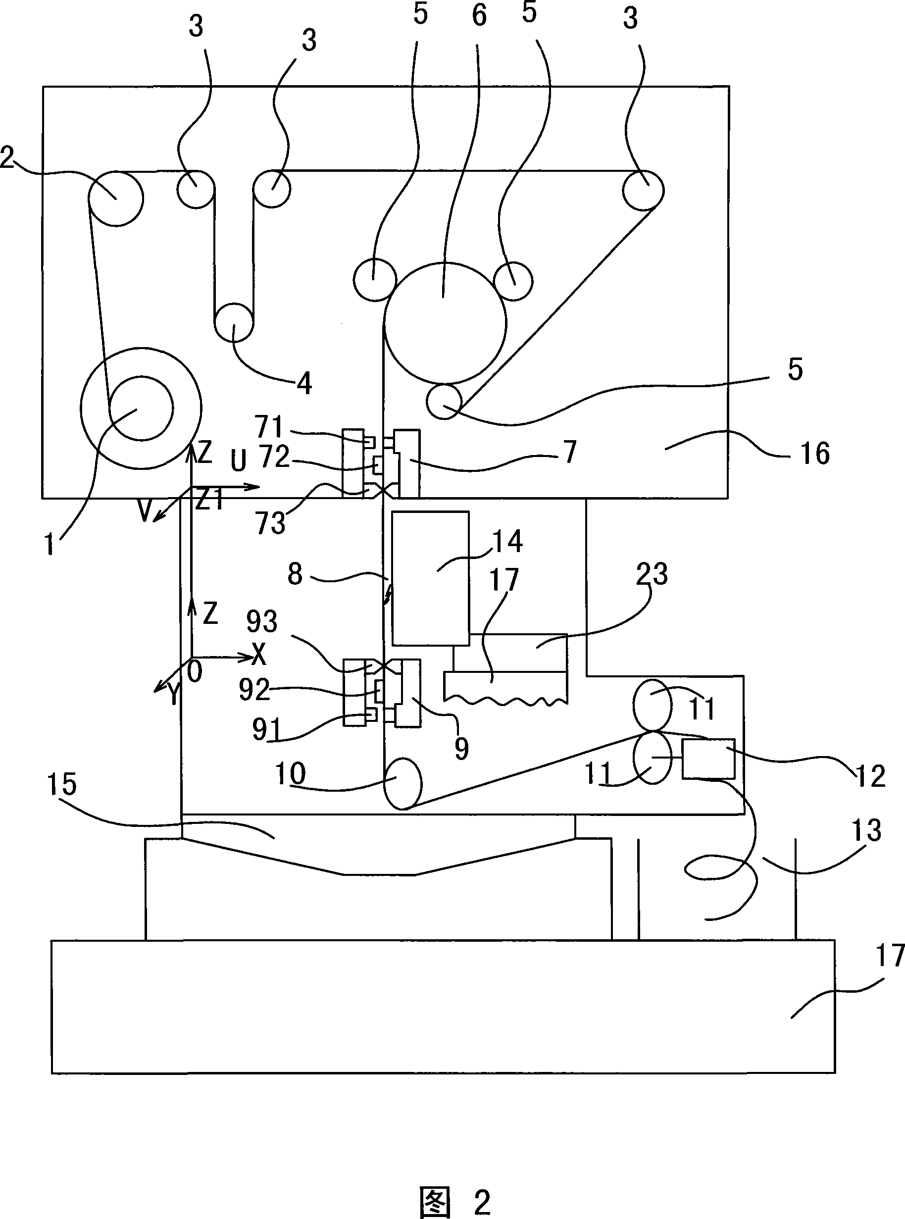
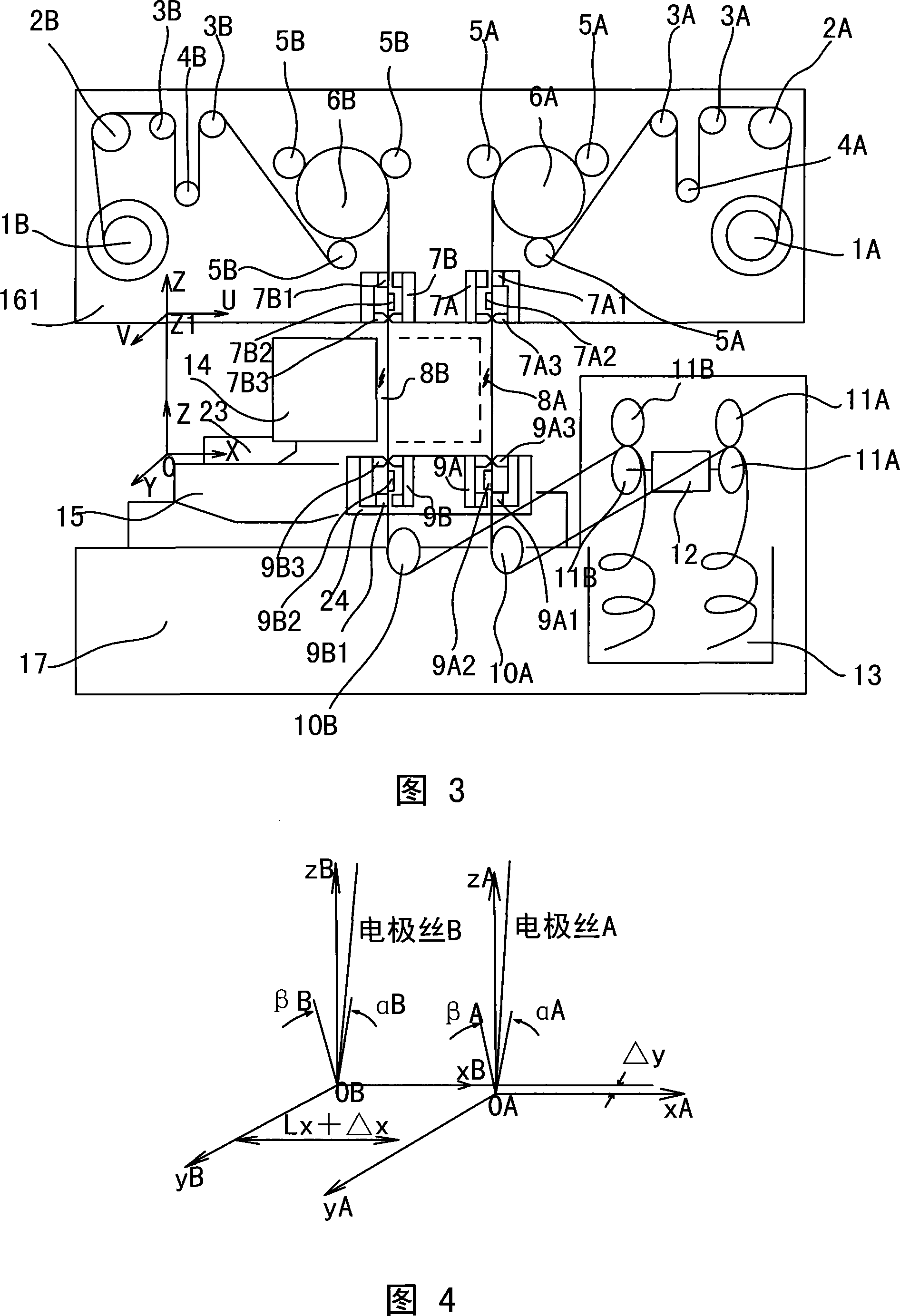
[0036] As shown in Figure 3, the double three-dimensional position coordinate line cutting electric discharge machining device includes a bed 17, an X-Y axis movement carriage 15, a U-V-Z axis movement carriage and an upper guide wire assembly mounting plate 161, a workbench 23 and a lower guide wire assembly. Mounting plate 24. The U-V-Z axial movement carriage and the upper guide wire assembly mounting plate 161 are connected to the bed 17 through the column, the workbench 23 is installed on the X-Y axis movement carriage 15, the bottom surface of the X-Y axis movement carriage 15 is connected with the bed 17, and the lower The guide wire assembly mounting plate 24 is fixedly arranged on the bed 17 through the lower wire arm. The workpiece 14 is mounted on the workbench 23 and located between the upper guide wire assembly mounting plate 161 and the lower gu...

Embodiment 2

[0040] Embodiment 2: Another double-three-dimensional position coordinate system wire-cut electric discharge machining device.

[0041] As shown in Figure 5, another double-three-dimensional position coordinate system wire-cut EDM device includes a bed 17, an X-Y axis moving carriage 15, a U-V-Z axis moving carriage and an upper guide wire assembly mounting plate 161, a workbench 23, The lower guide wire assembly mounting plate 24 and two sets of wire feeding mechanisms that cannot be used at the same time. The two sets of wire feeding mechanisms have their own feeding and receiving parts and upper and lower wire guide assemblies. The two upper guide wire assemblies of the two sets of wire feeding mechanisms are all installed on the upper guide wire assembly mounting plate 161 in front of the same U-V-Z axis moving carriage. The two lower guide wire assemblies of the two sets of wire feeding mechanisms are all installed on the same lower guide wire assembly mounting plate 24 ...

Embodiment 3

[0044] Embodiment 3: This embodiment is a practical improvement of the first embodiment. Both sets of wire feeding mechanisms adopt unidirectional low-speed wire feeding mechanisms.

[0045] In the first embodiment, two sets of completely separated and independent wire feeding components are used, and the two three-dimensional position coordinate systems have a fixed difference Lx in the X-axis direction in the horizontal plane. The two lower guide wire assemblies 9A, 9B are all fixed on the lower guide wire assembly mounting plate 24, and the lower guide wire assembly mounting plate 24 is installed on the front end of the upper wire arm fixed on the bed. Due to the limitation of the size of the front end of the lower wire arm and the size of the lower guide wire assembly mounting plate 24, Lx is generally controlled at a value of about 80-150mm, and the diameter of the polyurethane wheel equipped with a tension controller is also at this value within range. In addition, in t...


PUM

PropertyMeasurementUnit
surface roughnessaaaaaaaaaa

Abstract

The invention provides a dual three-dimensional coordinate line cutting discharge processing device, which consists of two sets of wire movement systems which are not used at the same time; the two upper wire guiding components in the two sets of wire guiding mechanisms are both arranged on an upper wire guiding component installation plate; the two lower wire guiding components are arranged on a lower wire guiding component installation plate. Therefore, the invention establishes the two three-dimensional position coordinate system which consists of two sets of X, Y, U, V, Z five coordinate axises and is formed by the electrode wire section between the upper wire guiding component and the lower wire guiding component corresponding to the workpiece in space position relation; the origin of each coordinate system is the center of the wire guiding hole of respective lower wire guiding elements. A fixed distance L in an X-Y plane is arranged between the origins of the two coordinate systems. When the rough cutting process of the first wire movement mechanism is achieved by a rough wire electrode, an X-Y axis motion trailing bar moves the fixed distance L correspondingly in the X-Y horizontal plane, thus leading the three-dimensional position coordinate system of the second wire movement mechanism to be coincident to the three-dimension position coordinate system of the first wire movement mechanism; a precise cutting discharge process is achieved to the profile of the workpiece for a plurality of times by fine electrode wire of the second wire movement mechanism, thus achieving the cutting process for a plurality of times to the same workpiece sequentially by the two wire movement mechanisms.

Description

technical field [0001] The invention relates to a wire-cut electric discharge machining device, in particular to a wire-cut electric discharge machining device with a double three-dimensional position coordinate system that uses one kind of electrode wire for rough cutting and then uses another kind of electrode wire for fine cutting. Background technique [0002] Wire-cut electric discharge machining is the main processing method for metal molds and conductive special materials. It uses the electric erosion effect produced by electric spark discharge to carry out cutting processing. Such devices are usually composed of four major parts: mechanical movement mechanism, pulse power supply, numerical control system and working fluid supply system. The mechanical movement mechanism is mainly composed of bed, wire transporting parts, U-V-Z axis movement carriage and X-Y axis movement carriage. In order to realize the cutting process of three-dimensional contour shape, the device...

Claims


Application Information

Patent Timeline
Patent Type & Authority Applications(China)
IPC IPC(8): B23H7/26B23H7/10
Inventor 顾元章
Owner 泰州市海通资产管理有限公司
Why Eureka
Try Eureka