
Vacuum closet discharging device

A technology for vacuum toilets and equipment, which is applied to flushing equipment with water tanks, water supply devices, buildings, etc., can solve the problems of humid use environment, increased water consumption, unstable use performance, etc., and achieve stable operation performance and overall performance improvement. , good suction and discharge effect

Inactive Publication Date: 2008-07-23
704TH RES INST OF CHINA SHIPBUILDING IND CORP
View PDF2 Cites 10 Cited by
  • Summary
  • Abstract
  • Description
  • Claims
  • Application Information

AI Technical Summary

Problems solved by technology

[0002] The vacuum toilet control components of the existing vacuum flush toilets mostly use electronic components, but due to the humid use environment, the electronic components are easily damaged, resulting in extremely unstable performance, and the practicability of these devices has been questioned; in this regard, the industry has developed The use of pneumatic control components is also difficult to popularize and apply due to problems such as complex structure and difficult assembly and maintenance; in view of the above problems, the Chinese patent name is "A Vacuum Flush Toilet" and the patent number is 00223791.1. A new technical solution is proposed. The scheme includes a starting device, a control device, a vacuum toilet and a vacuum feces collection tank, wherein: the starting device is composed of an opening button and an emergency button, and the opening button is connected with a pressure piston and the control device, and its reset is simply a return spring; the control The device has a number of air chambers formed in its housing, a push rod runs through each air chamber, the main and auxiliary valves are fixed on the push rods in turn, and the top of the push rod is provided with a return spring, which is held on the housing to cooperate with each The air flow in the air chamber, the discharge valve and the flush valve of the vacuum toilet are closed under the action of the return spring to complete a working cycle of the control device; the vacuum toilet is composed of a discharge valve, a flush valve and a toilet. No. 3,984,080) are basically the same in structure and will not be described in detail. Its flush valve structure is similar to that of the Swedish product EVAC. The water inlet and outlet of this product are controlled by a diaphragm piston. The action of the diaphragm piston is: The vacuum degree of the air chamber and the suction of the rubber membrane of the piston and the magnetic component will open the diaphragm piston, and the water inlet and outlet will disappear when the above vacuum degree disappears. Under the action of the return spring, the rubber membrane of the piston will return to its original position, the magnetic component will be separated, and the diaphragm will be closed. The piston and the water inlet and outlet are broken. Another structural feature of this product is that the air chamber and the water chamber are composed of two shells respectively; the above technical solution has the following problems:
[0003] 1. Although the structure of the opening button is simple, its reset (that is, cut off after the air is pressed to the control device) is completed by the return spring, which has nothing to do with the function of the control device. Have a negative impact;
[0004] 2. The key components of the control device are the push rod and its return spring. The force of the spring directly affects the opening or closing of the main and auxiliary valves, as well as the functions of the associated air chambers. Since the force is a constant value that cannot be adjusted, Any deviation in processing, assembly, and material may affect the action of the push rod, thereby affecting the effectiveness of the functions of subsequent components such as flush valves and discharge valves;
[0005] 3. The flush valve only relies on the vacuum degree and the return spring to control the opening and closing of the diaphragm piston. Due to its limited function, the action of the flush valve is slow, which may cause unstable performance, unclean suction and discharge, and increased water consumption.

Method used


Image

  • Vacuum closet discharging device
  • Vacuum closet discharging device
  • Vacuum closet discharging device

Examples


Embodiment Construction

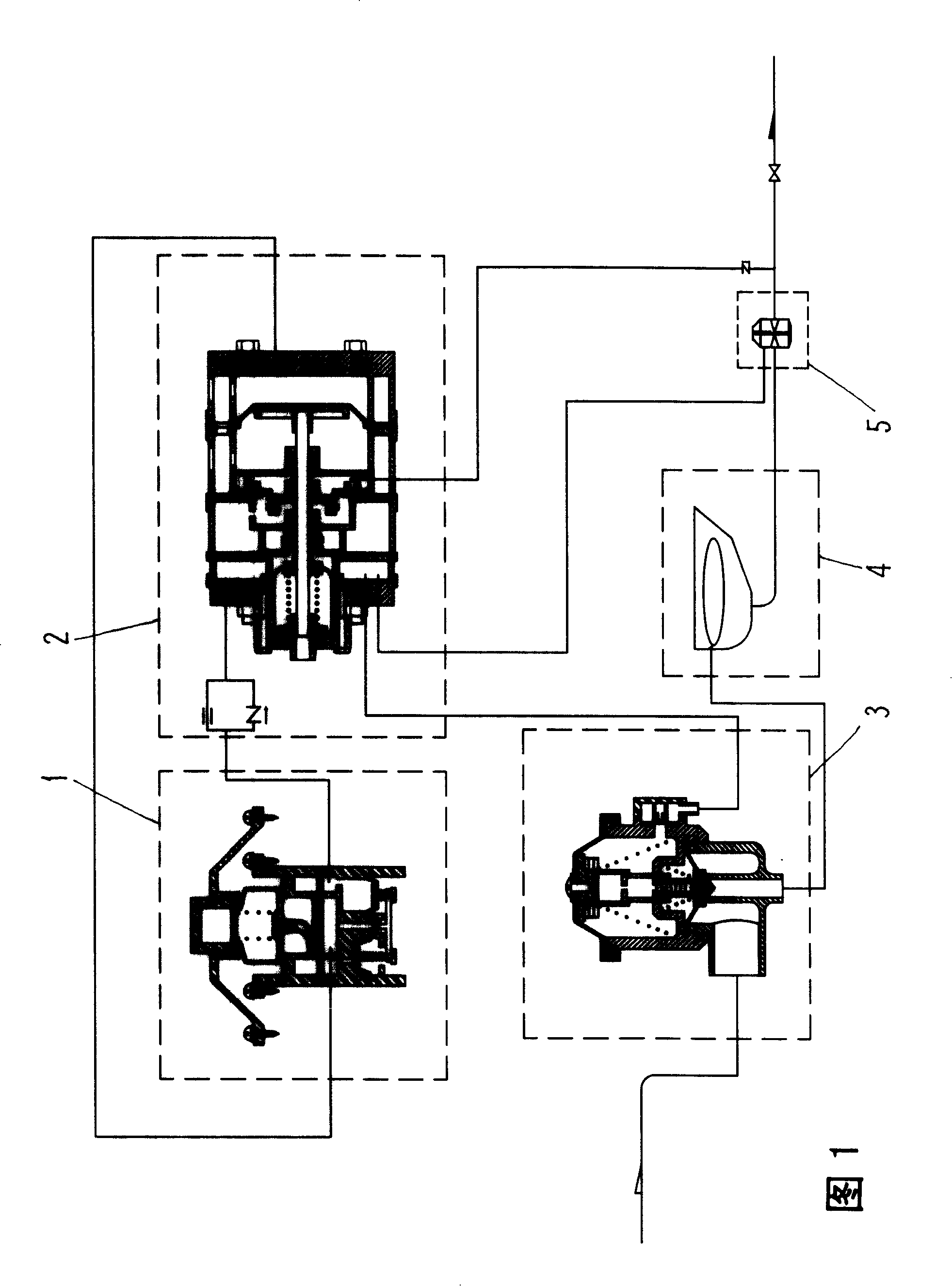
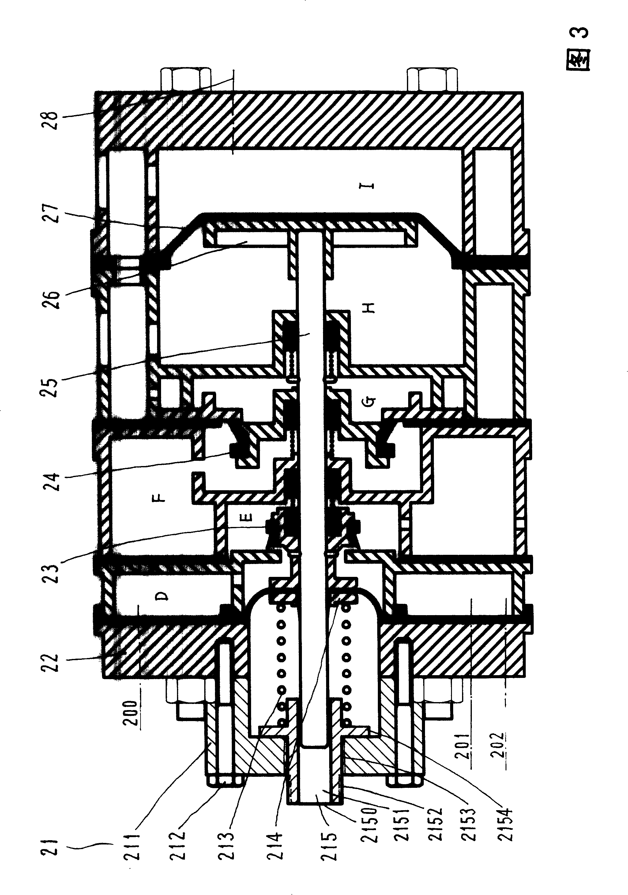
[0014] Referring to Fig. 1, the vacuum toilet discharge equipment includes a starting mechanism 1, an actuator 2, a flush valve 3, a vacuum toilet 4, a vacuum discharge valve 5 and a collection cabinet (not shown); the starting mechanism 1 is connected to the actuator 2 through a pipeline , the actuator 2 is respectively connected with a flush valve 3 and a vacuum discharge valve 5 through a pipeline, the flush valve 3 is connected with a vacuum toilet 4 through a pipeline, the vacuum toilet 4 is connected with a vacuum discharge valve 5 through a pipeline, and the vacuum discharge valve 5 is connected with a feces collection cabinet.

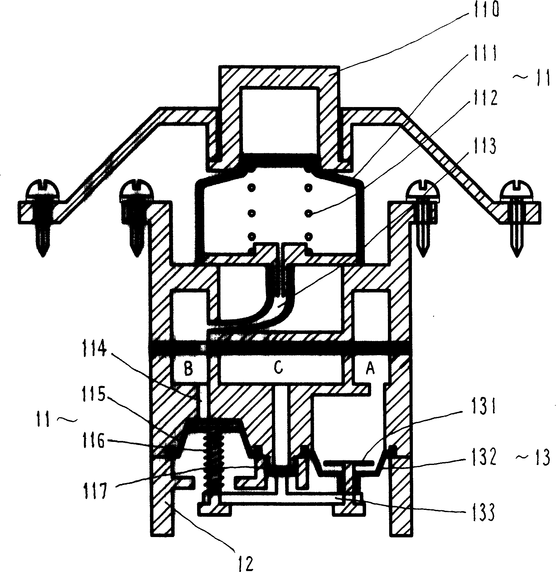
[0015] The starting mechanism 1, as shown in Figures 1 and 2, includes a starting action assembly 11, a cylinder body 12 and a reset assembly 13, wherein:

[0016] The starting action assembly 1 includes a button 110, an air bag 111, a spring 112, a conduit 113, a channel 114, a starting membrane 115, a starting lever 116, and an intake valve 1...


PUM


Abstract

The invention relates to a vacuum toilet bowl drainage apparatus, mainly solving the technical problems of pneumatic controled toilet in flushing and drainage functions; the adopted technical proposal is that a resetting component which is connected with an executive device is positioned on the cylinder body of a starting device of the drainage apparatus, the rear end of a push rod of the executive device of the drainage apparatus is provided with a restoring force regulation component; a reset spring is arranged inside the gas chamber L of a flushing valve of the drainage apparatus and the gas chamber L is communicated with atmosphere, the spring props against the casing and a diaphragm piston of the valve component; the vacuum toilet bowl drainage apparatus is applicable to various vacuum toilet bowls.

Description

Technical field: [0001] The present invention relates to a flushing device with a pressure operated storage tank, in particular a vacuum toilet. Background technique: [0002] The vacuum toilet control components of the existing vacuum flush toilets mostly use electronic components, but due to the humid use environment, the electronic components are easily damaged, resulting in extremely unstable performance, and the practicability of these devices has been questioned; in this regard, the industry has developed The use of pneumatic control components is also difficult to popularize and apply due to problems such as complex structure and difficult assembly and maintenance; in view of the above problems, the Chinese patent name is "A Vacuum Flush Toilet" and the patent number is 00223791.1. A new technical solution is proposed. The scheme includes a starting device, a control device, a vacuum toilet and a vacuum feces collection tank, wherein: the starting device is composed o...

Claims


Application Information

Patent Timeline
Patent Type & Authority Applications(China)
IPC IPC(8): E03D3/10E03D3/02E03D5/09E03D1/34
Inventor 陈清齐建林巍
Owner 704TH RES INST OF CHINA SHIPBUILDING IND CORP
Learn More