
LED lighting device capable of recovery heat

A technology of LED lighting and heat recovery, which is applied in the direction of lighting devices, components of lighting devices, cooling/heating devices of lighting devices, etc., can solve the problems of high cost, low heat dissipation efficiency, bulky appearance, etc., and achieve heat dissipation cost reduction, The effect of reducing the volume and expanding the application range

Inactive Publication Date: 2008-07-23
XI AN JIAOTONG UNIV
View PDF0 Cites 45 Cited by
  • Summary
  • Abstract
  • Description
  • Claims
  • Application Information

AI Technical Summary

Problems solved by technology

[0005] Aiming at the disadvantages of the two heat dissipation methods of the current LED lights, such as high cost, bulky appearance, and low heat dissipation efficiency, the present invention provides an LED lighting device that can recover heat dissipation energy, which can not only realize high-efficiency heat dissipation, but also convert part of the waste heat to make it Turn into electric energy reuse to achieve the purpose of energy saving

Method used


Image

  • LED lighting device capable of recovery heat
  • LED lighting device capable of recovery heat

Examples


Embodiment Construction

[0015] The present invention will be further described in detail below in conjunction with the accompanying drawings and specific embodiments.

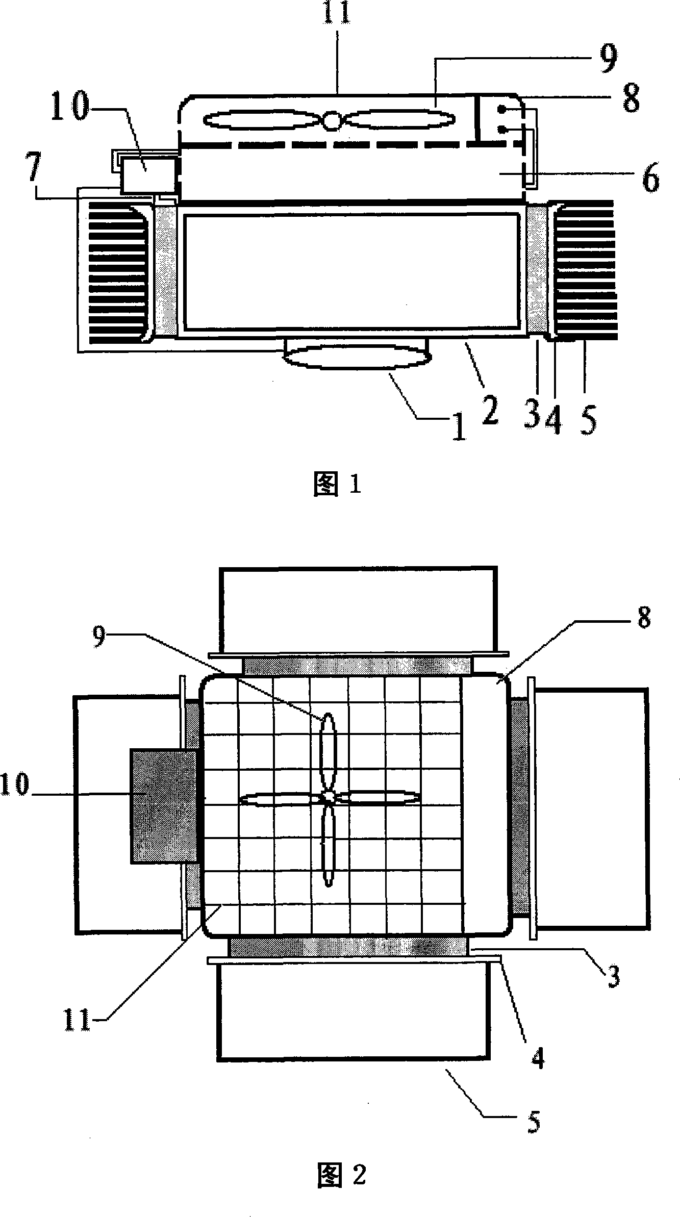
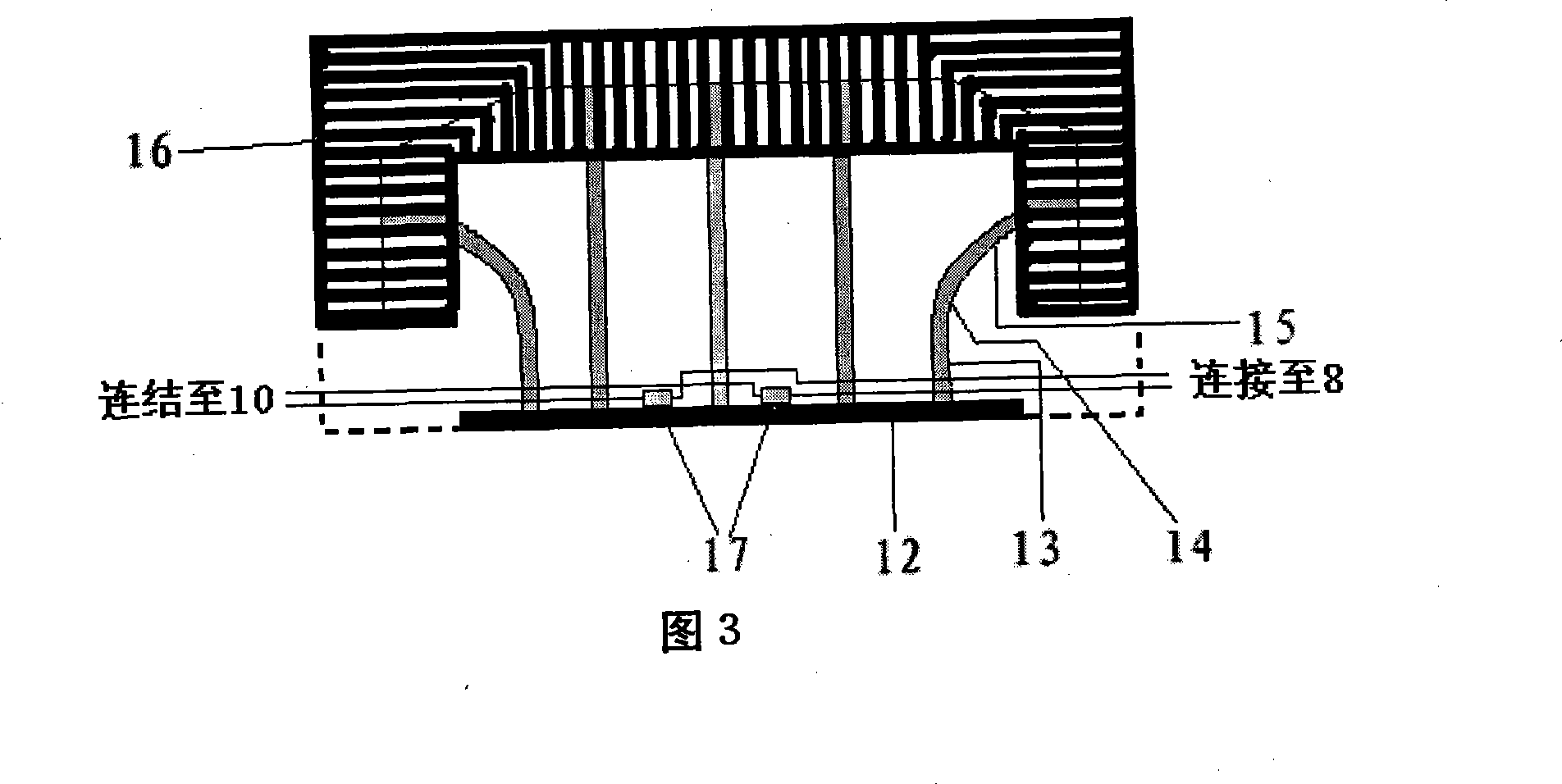
[0016] As shown in Figure 1 and Figure 2, an LED lighting device that can recover heat dissipation energy is composed of an LED planar light source, a heat dissipation part, and a thermoelectric conversion part. The heat dissipation part includes a box-shaped inner base plate 2 for uniform heat, a heat pipe radiator 6 and a heat dissipation fan 9 and a fan connector 8 arranged thereon. Two bimetal strip temperature switches 17 on the aluminum seat plate 12 of the device 6 (the temperature on the plate is basically the same as the temperature of the LED plane light source) are controlled by the fan connector 8 . The back of the LED planar light source 1 is closely attached to the lower surface of the closed box-shaped inner substrate 2 , and the heat pipe radiator 6 is closely attached to the upper surface of the box-shaped inner subst...


PUM


Abstract

The invention discloses a LED illuminating device capable of heat recovery, comprising an LED flat panel light source, a heat-dissipation device and a thermoelectricity conversion device; the heat-dissipation device comprises a closed box-shaped inner base plate, a heat pipe radiator and a cooling fan which is positioned above the heat pipe radiator; the backside of the LED flat panel light source is closely attached on lower surface of the inner base plate and the heat pipe radiator is closely attached on upper surface of the inner base plate; the thermoelectricity conversion device comprises a plurality of outer base plates which are arranged around the outside of the inner base plate and heat dissipation fins are arranged on outer lateral surfaces of each outer base plate; sheet-type thermoelectricity converters are arranged between inner lateral side of each outer base plate and outer lateral side of each inner base plate, the side where the thermoelectricity converter is closely attached on the outside is heat end and the side where the thermoelectricity converter is closely attached on the inner side is cold end; the heat end and cold end of each thermoelectricity converter are series-connected, parallel-connected or series-parallel connected and then are connected via output wires with an energy-storage conversion unit arranged at one side of a radiator; the energy storage conversion unit can distribute electric energy to LED flat panel light source for auxiliary lightening and can drive the operation of cooling fan.

Description

technical field [0001] The invention relates to an LED lighting device capable of realizing heat recovery. Background technique [0002] Compared with other light sources, LED [light-emitting diode] lighting has the advantages of high luminous intensity, energy saving and energy saving. It has developed rapidly in recent years, and the industrial scale has continued to expand. However, with the market's demand for high-power LED lighting devices, the problem of LED heat dissipation has become a bottleneck restricting the development of the industry. [0003] At present, LED lights on the market mainly rely on natural heat dissipation. From the perspective of heat transfer, natural heat dissipation uses natural convection and thermal radiation as the basic heat dissipation principles. In natural heat dissipation, the basic idea is to use the outer wall of the lamp, especially the fins to convect the surrounding air and radiate heat to the surrounding objects. This form of h...

Claims


Application Information

Patent Timeline
Patent Type & Authority Applications(China)
IPC IPC(8): F21V29/00F21V29/02F21V17/00H01L23/34F21Y101/02F21V29/67F21V29/74F21Y105/10F21Y115/10
CPCH01L2924/0002
Inventor 胡红利徐通模惠世恩刘斐
Owner XI AN JIAOTONG UNIV
Learn More