Salinity sensor using ionic conductance ratio, salinity measuring system and method

A technology of ion conductivity and measurement system, which is applied in applications, household appliances, buildings, etc., can solve problems such as low salinity, different salinity, and reduced reliability of measurement data

Inactive Publication Date: 2008-07-23
LG ELECTRONICS INC
View PDF0 Cites 10 Cited by
  • Summary
  • Abstract
  • Description
  • Claims
  • Application Information

AI Technical Summary

Problems solved by technology

[0007] However, the method of measuring salinity based on the conventional conductivity of ions supplies a partial DC component to the measurement probe in the salinity sensor while continuously measuring salinity, resulting in the ions (Na + , Cl - ) accumulates on the measuring probe over time, thus reducing the ionic conductivity
[0008] Therefore, this method poses a problem that, due to the ions (Na + , Cl - ) reduces the ionic conductivity so that even when measuring samples with the same salinity, the salinity is different each time the measurement is made, and the measured salinity is lower than the actual salinity, thereby reducing the reliability of the measurement data
[0009] In addition, before measuring the salinity of food or solution, conventional measuring devices must have complicated steps such as using a variable resistor to set the resistance value, so that it is difficult for ordinary users to directly measure salinity by using a variable resistor
[0010] The salinity sensor is not inherently installed in the container of food or solution in the measuring device, but is installed in a separate tool box, so that it is extremely troublesome for the user to measure the salinity of the food or solution in the container

Method used


Image

  • Salinity sensor using ionic conductance ratio, salinity measuring system and method
  • Salinity sensor using ionic conductance ratio, salinity measuring system and method
  • Salinity sensor using ionic conductance ratio, salinity measuring system and method

Examples


Embodiment Construction

[0029] In the following, the detailed description is by way of example only and illustrates various embodiments of the invention. In addition, the detailed description is provided in order to properly and easily explain the principles and concepts of the present invention.

[0030] Therefore, detailed structures not necessary for a basic understanding of the invention are not provided. Various forms of embodiments of the invention that can be practiced by those skilled in the art are illustrated by the drawings.

[0031] Hereinafter, embodiments of the present invention will be described in more detail with reference to the accompanying drawings.

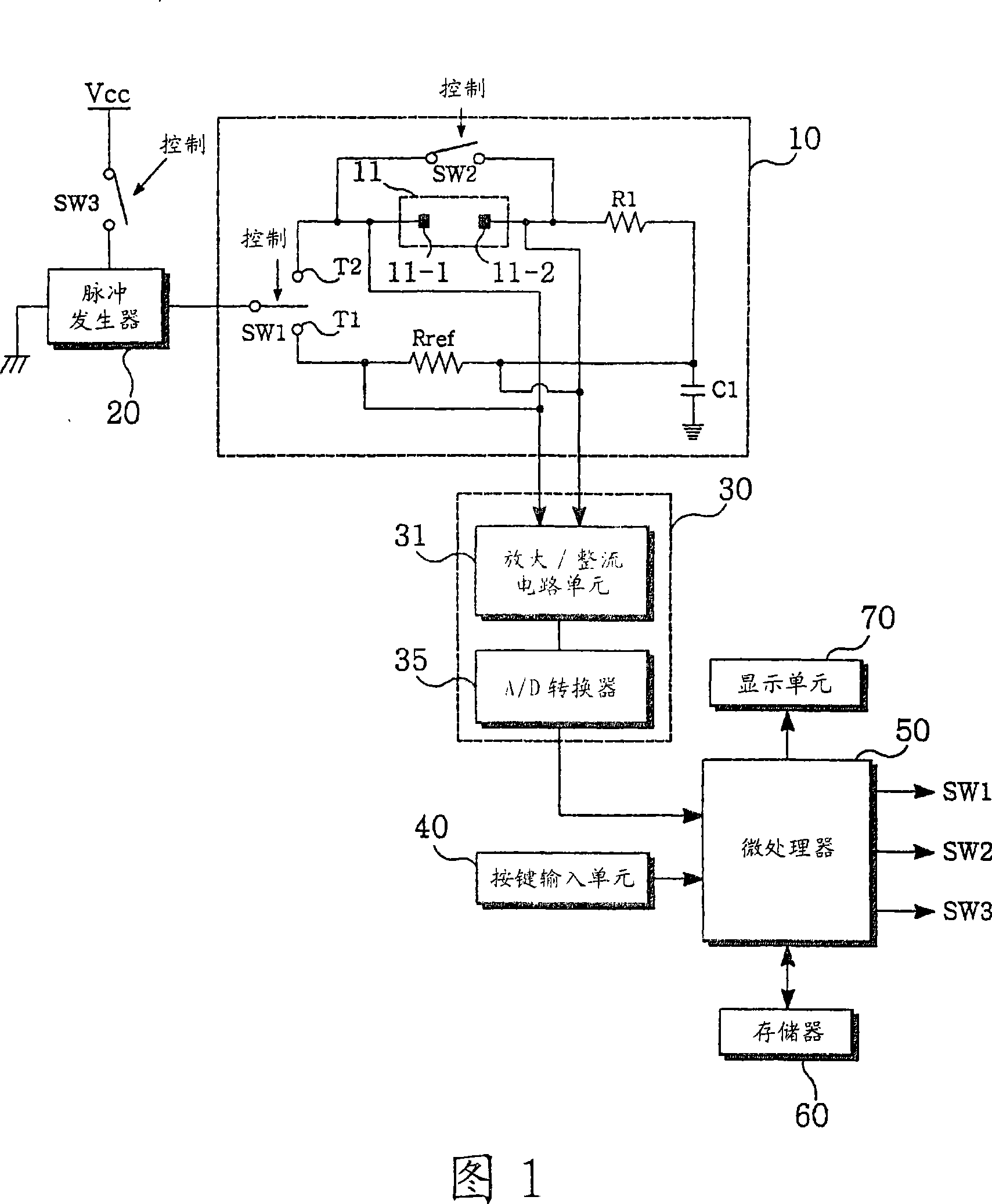
[0032] FIG. 1 is a view showing a salinity measurement system using ion conductivity according to the present invention. The salinity measurement system includes a salinity sensor 10 , a pulse generator 20 , a detection signal processing unit 30 , and an operation control unit 50 .

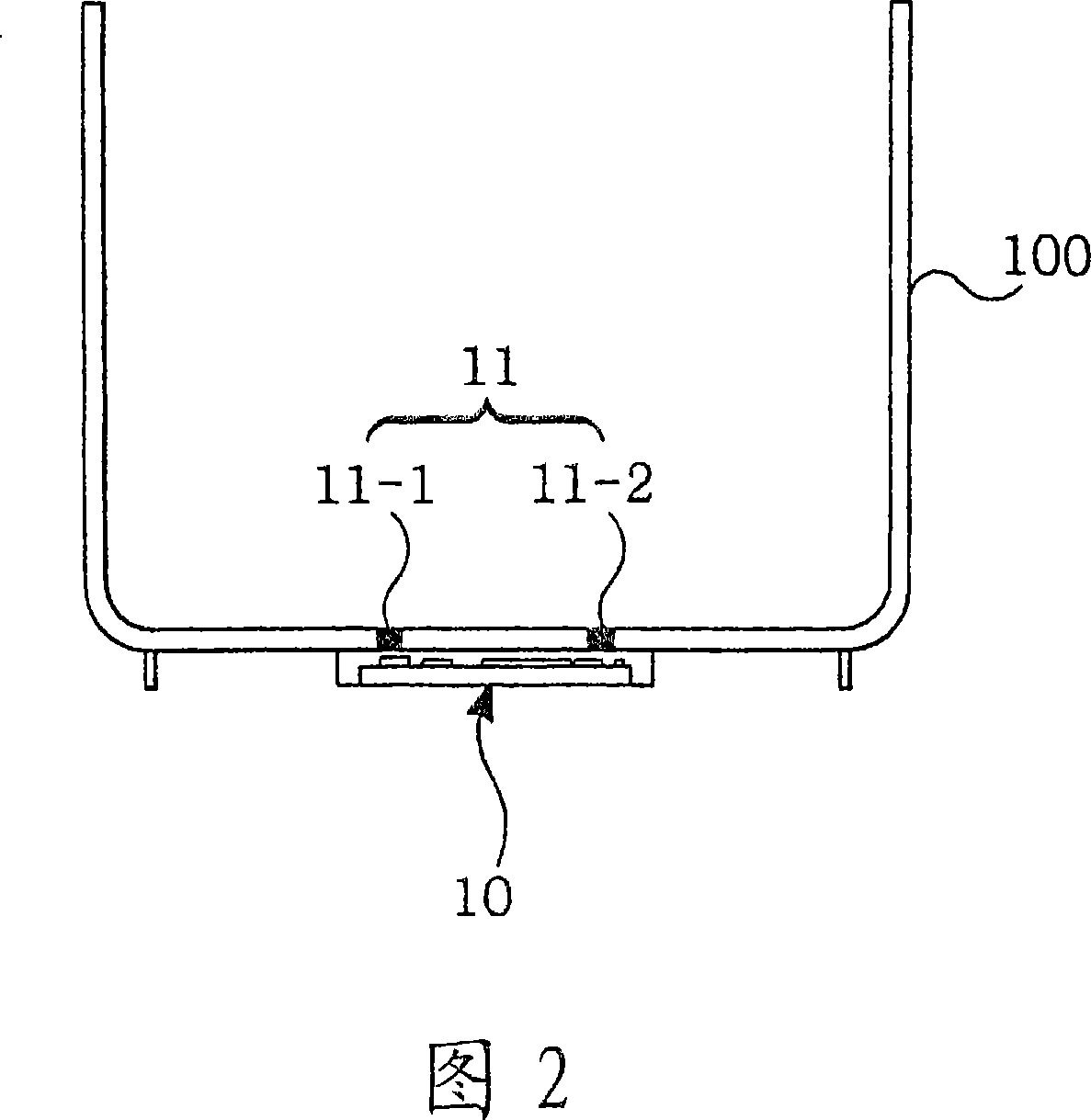
[0033]The salinity sensor 10 includes a first ...


PUM


Abstract

The invention discloses a salinity sensor using ionic conductivity, salinity measuring system and method thereof, wherein the salinity sensor is mounted in a container for storing food or solution, in order to prevent the chlorine ion conductivity from descending due to ion accumulating in the probe along with the measuring time lapsing during measuring the salinity, the ion accumulating in the probe is arbitrarily released to prevent the salinity measurement error from generating.

Description

technical field [0001] The present invention relates to salinity measurement, and more particularly, to a salinity sensor utilizing ionic conductivity, a salinity measurement system and a method thereof to prevent the ion Accumulation causes degradation of sodium ions and chloride ions leading to salinity measurement errors and makes salinity measurement easier by placing the salinity sensor directly in the food or solution container. Background technique [0002] Generally, there are three methods for measuring salinity in food or solution as follows: [0003] First, when the measuring device measures salinity using a refractive index scheme, the measuring device calculates salinity by collecting, in a photoelectric sensor, laser light generated from a laser module and refracted by a sample. Since the refractive index changes as the salinity in the sample changes, the measuring device calculates the salinity in the sample by measuring the refractive index. [0004] Howeve...

Claims


Application Information

Patent Timeline
Patent Type & Authority Applications(China)
IPC IPC(8): G01N27/04
CPCA47K1/04E03C1/264
Inventor 郑一炯尹周焕金真阿金钟大
Owner LG ELECTRONICS INC
Why Eureka
Try Eureka