
Method and system for locating gaze type camera motor point goal

A technology of camera movement and positioning method, which is applied in image data processing, instrumentation, computing, etc., can solve the problems of reducing signal-to-noise ratio and increasing system complexity, and achieve the goal of improving signal-to-noise ratio, facilitating precise positioning, and reducing random noise effect of influence

Active Publication Date: 2008-07-23
SHANGHAI INST OF TECHNICAL PHYSICS - CHINESE ACAD OF SCI
View PDF0 Cites 6 Cited by
  • Summary
  • Abstract
  • Description
  • Claims
  • Application Information

AI Technical Summary

Problems solved by technology

This approach, in addition to increasing the complexity of the system, will also reduce the signal-to-noise ratio by reducing the energy reaching each focal plane

Method used


Image

  • Method and system for locating gaze type camera motor point goal

Examples


Embodiment Construction

[0014] The speed of the moving point object for this embodiment is about 7 pixels per second.

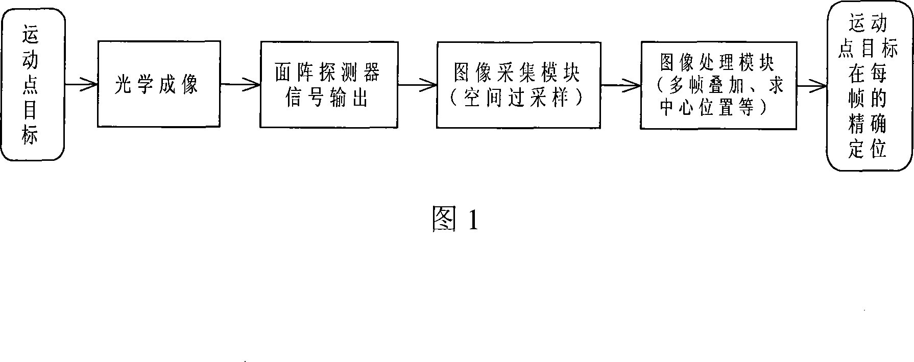
[0015] The staring camera movement point target precise positioning system adopted specifically includes:

[0016] Optical imaging system: The main parameters of the telescopic imaging optical system are:

[0017] Caliber 90mm;

[0018] The focal length is 270mm.

[0019] Detector: 512×512 element mid-wave infrared focal plane detector. The frame rate of the detector is adjustable, and the highest frame rate can reach 100Hz.

[0020] Image acquisition module: set the frame frequency of the detector to 50Hz, and collect an image of the point target approximately every 0.14 pixels. Transfer the acquired sequence of images to the designated cache space in the computer memory.

[0021] Image processing module: Write a program on the computer, and perform the following algorithm processing on the sequence images of moving point targets after spatial oversampling.

[0022] 1. Perfor...


PUM


Abstract

The invention discloses a target location method and a system of starting camera movement points. The target location method comprises 1 carrying out space oversampling to movement point targets by using high frame rate character of the staring camera, 2 carrying multi-frame superposition to collected sequence images, 3, on the basis of multi-frame superposition, detecting and extracting small target spots, and then acquiring the central point of the small target points with sub-pixel processing method. The system includes an optical imaging system, a flat panel detector, an image collecting module and an image processing module, wherein the image collecting module realizes space oversampling to movement point target, the image processing module carries out multi-frame superposition, aiming at collected sequence images, carries out small target spots detecting, extracting and acquires the central position of point targets with sub-pixel method and the like.

Description

technical field [0001] The invention relates to space target positioning technology, in particular to a staring camera moving point target positioning method and system, which is used for positioning small space moving targets. Background technique [0002] In engineering applications, it is required to be able to find targets at a long distance. At this time, the target appears in the form of a point target in the field of view. To improve the positioning accuracy of point targets, the pixel resolution of area array detectors should be considered first. However, due to the limitations of the manufacturing process, it is difficult to increase the pixel resolution of the area array detector; in addition, due to the limitation of the diffraction effect, the resolution of the detector cannot be infinitely improved. At the same time, the filling factor of the area array detector is not 100%, which will affect the positioning accuracy of the point target. Now there are still s...

Claims


Application Information

Patent Timeline
Patent Type & Authority Applications(China)
IPC IPC(8): G06T7/20G06T7/00
Inventor 潘鸣石勋裴云天冯翔龙卓瑜李建林张荣锋侯丽伟郑新波王钢谢巍
Owner SHANGHAI INST OF TECHNICAL PHYSICS - CHINESE ACAD OF SCI
Learn More