Double coil various current control method for vacuum breaker permanent magnetism mechanism

A technology of vacuum circuit breaker and permanent magnet mechanism, applied in the direction of protection switch operation/release mechanism, electromagnet, electromagnet with armature, etc., which can solve the problem of long operating time, insufficient opening speed, scattered opening and closing time to reduce the kinetic energy and collision speed of the iron core and improve the electrical life

Inactive Publication Date: 2008-07-23
XI AN JIAOTONG UNIV +1
View PDF0 Cites 3 Cited by
  • Summary
  • Abstract
  • Description
  • Claims
  • Application Information

AI Technical Summary

Problems solved by technology

High-voltage circuit breakers require faster action speeds. Under the condition of a certain number of ampere-turns, in order to properly reduce the current, the number of turns can only be increased. The more turns of the coil, the greater the inductance, and the current rises to the action requirement. The longer the current time, the longer the action time will be, which will increase the dispersion of opening and closing time, and cannot meet the requirements of synchronous closing
[0004] The existing mechanism design generally focuses on the rationality of the structure so that the characteristics of the permanent magnet mechanism can be well matched with the characteristics of the vacuum circuit breaker. However, the traditional single-coil control strategy obviously cannot overcome the excessive current, long operating time, rigid The defect of insufficient sub-speed

Method used


Image

  • Double coil various current control method for vacuum breaker permanent magnetism mechanism
  • Double coil various current control method for vacuum breaker permanent magnetism mechanism
  • Double coil various current control method for vacuum breaker permanent magnetism mechanism

Examples


Embodiment Construction

[0023] The present invention will be described in further detail below in conjunction with the accompanying drawings.

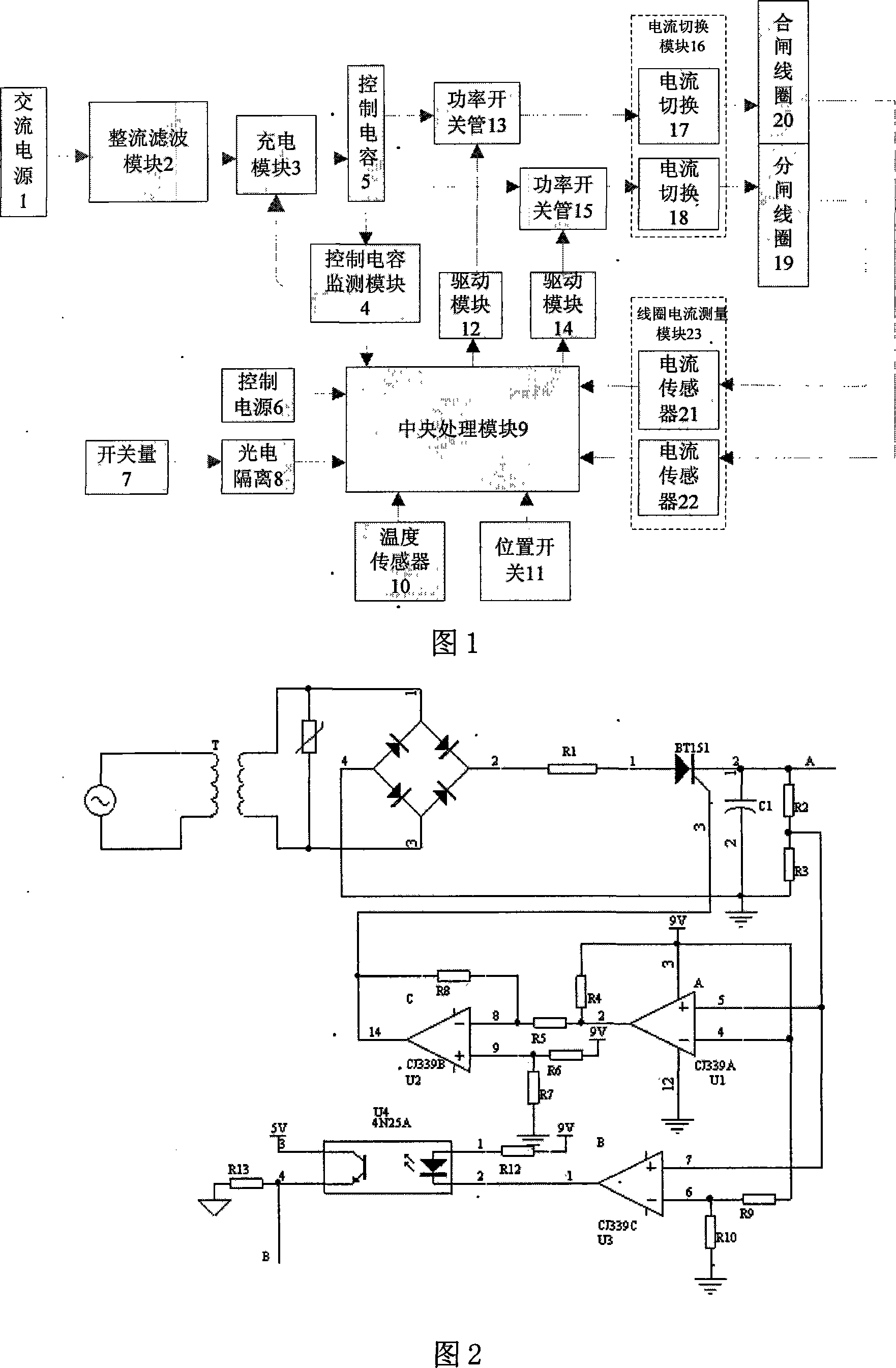
[0024] Referring to Fig. 1, the present invention comprises the rectifying and filtering module 2 that is connected with AC power supply 1, the output end of this rectifying and filtering module 2 is connected with the current input end of charging module 3, the output end of charging module 3 is connected with the input of control capacitor 5 The voltage feedback terminal of the control capacitor 5 is connected with the input terminal of the control capacitance detection module 4, the signal output terminal of the capacitance detection module 4 is connected with the signal input terminal of the charging module 3, and the other output terminal of the capacitance detection module 4 It is connected to the signal input end of the central processing module 9 for monitoring and controlling the state of the control capacitor detection module 4, and the current outpu...


PUM


Abstract

Disclosed is a current varying control method of double-coil of permanent mechanisms of vacuum circuit breakers. In closing process, a trip coil is reversely galvanized to offset a part of permanent magnet retaining force, to reduce closing action current, simultaneously adjust the current of a closing coil, and reduce iron core kinetic energy on the premise of ensuring instantaneous closing speed. In switching off time, the trip coil is directly galvanized, the closing coil is reversely galvanized or the trip coil is directly galvanized and the closing coil is directly galvanized. Voltage and current of the trip coil and the closing coil are sampled by a coil current measuring module, and collected data is fed back to a central control module. A central treatment module calculates rate of current change in current coils and adjusts current value in the trip coil according to calculated result. The invention adjusts current amplitude in coils by sampling feedback of current and voltage of the trip coil and the closing coil of a permanent mechanism, and enables the operating characteristic of the permanent mechanism and the spring load characteristic of the circuit breaker to realize ideal engagement.

Description

technical field [0001] The invention belongs to the field of electronic applications, and in particular relates to a double-coil variable current control method of a permanent magnet mechanism of a vacuum circuit breaker. Background technique [0002] The bistable permanent magnet mechanism is a new type of operating mechanism designed for vacuum circuit breakers. It has attracted widespread attention because of its high reliability and small dispersion of opening and closing times, and it has been widely used in the medium-voltage field. Its main action features are: when the opening or closing signal is sent out, the power supply supplies power to the opening coil or closing coil, and the electromagnetic force generated by the coil overcomes the reaction force and permanent magnetic holding force, drives the iron core and then drives the circuit breaker contacts Complete opening and closing operations. After the action is completed, the permanent magnet provides the holdi...

Claims


Application Information

Patent Timeline
Patent Type & Authority Applications(China)
IPC IPC(8): H01H71/32H01H3/28H01F7/18
Inventor 耿英三王振兴王建华姚建军刘志远
Owner XI AN JIAOTONG UNIV
Why Eureka
Try Eureka