Heatable road

A technology for roads and heating elements, applied to roads, roads, on-site paved condensing pavements, etc., can solve problems such as low efficiency, snow and ice on the road area

Inactive Publication Date: 2008-07-30
卢启纯
View PDF0 Cites 16 Cited by
  • Summary
  • Abstract
  • Description
  • Claims
  • Application Information

AI Technical Summary

Problems solved by technology

Under the current technical conditions, it is only possible to shovel ice and snow manually by using various machines or tools. However, the

Method used


Image

  • Heatable road
  • Heatable road

Examples


Embodiment Construction

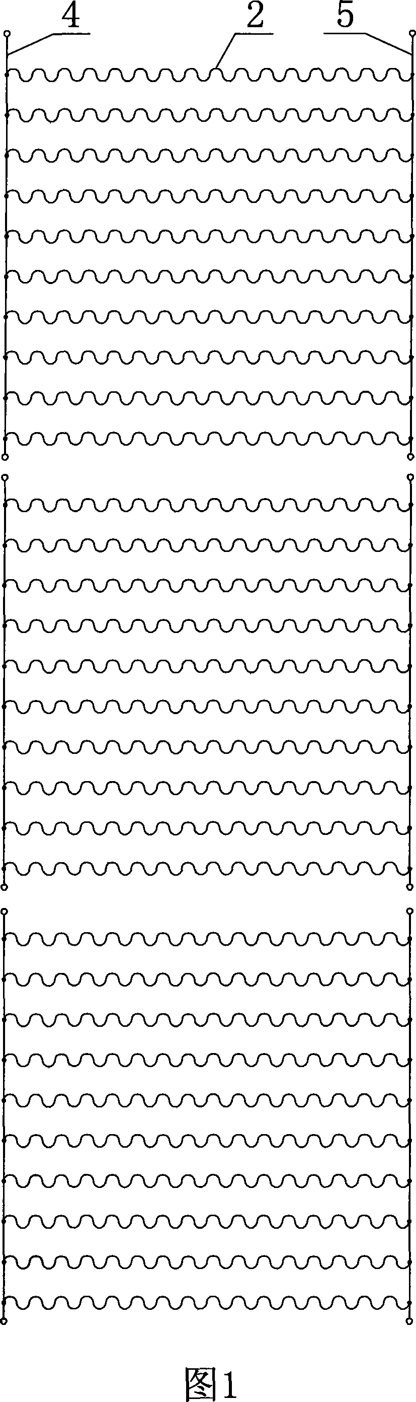
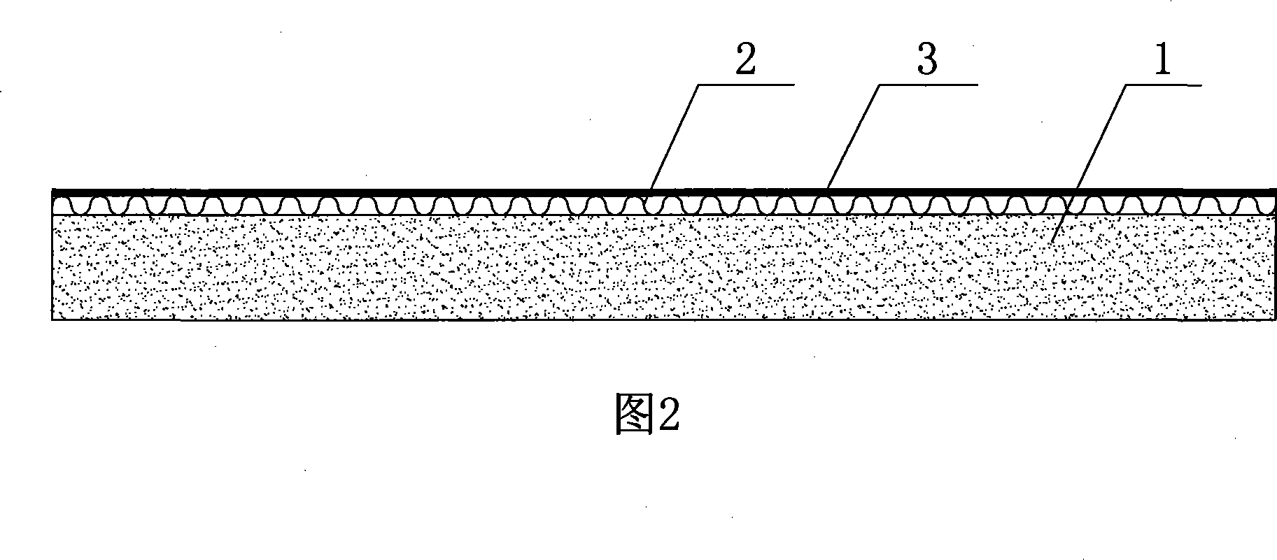
[0010] See shown in accompanying drawing 1~2, road of the present invention is made of three layers, and bottom layer is base layer 1, and middle layer is a plurality of reticular heating wires 2, and surface layer is asphalt protection layer 3, and one end of each heating wire It is connected with the positive aluminum wire 4 beside the road, and the other end is connected with the negative aluminum wire 5, and the heating wires are connected in parallel with each other.

[0011] During installation, first pour pure asphalt slurry on the surface of the base layer 1, spread the mesh heating wire 2, and then spread the special asphalt for paving. The mesh heating wire 2 can be divided into multiple sections, and the circuit of each section is independently controlled, which is convenient for daily maintenance. Through the low-voltage transformer, the alternating current is converted into 24 volts direct current to supply power to the heating wire mesh. The solution of the prese...


PUM


Abstract

The invention in particular relates to a road which can emit heat. The road is composed of three layers; wherein, a bottom layer is a foot layer, a middle layer is a heating element, and a superficial layer is a heat conduction protective layer; the heating element comprises a plurality of netty heating wires which are connected with each other in a parallel way; the heat conduction protective layer is a layer of asphalt. By utilizing the heating effect that the heating wires heat the road, the snow cover or the ice coating on the road are effectively avoided in winter, and the traffic safety of a car is supplemented.

Description

Technical field: [0001] The invention relates to the technical field of road structures, in particular to a heat-generating road. Background technique: [0002] In winter, it is snow and ice that pose the greatest threat to cars running on the road. Cars are prone to accidents when driving on snow or icy roads. Under the existing technical conditions, it is only possible to use various machines or tools to shovel ice and snow by manual methods, but the efficiency of this shovel is very low, and the shoveled road surface is easy to accumulate snow and freeze again. Invention content: [0003] The object of the present invention is to provide a heat generating road in order to overcome the above-mentioned deficiencies in the prior art. [0004] In order to achieve the above purpose, the technical solution provided by the utility model is: a heating road, the road is composed of three layers, the bottom layer is the base layer, the middle layer is the heating body, and the s...

Claims


Application Information

Patent Timeline
IPC IPC(8): E01C7/00E01C11/26
Inventor 卢启纯
Owner 卢启纯
Why Eureka
Try Eureka