Counting device, distance meter, counting method, and distance measuring method

A technology of counting equipment, distance meter, applied in the field of distance meter

Inactive Publication Date: 2008-07-30
YAMATAKE HONEYWELL CO LTD
View PDF0 Cites 10 Cited by
  • Summary
  • Abstract
  • Description
  • Claims
  • Application Information

AI Technical Summary

Problems solved by technology

[0014] Note that this counting error is not limited to rangefinders and may occur in other counting devices in the same way

Method used


Image

  • Counting device, distance meter, counting method, and distance measuring method
  • Counting device, distance meter, counting method, and distance measuring method
  • Counting device, distance meter, counting method, and distance measuring method

Examples


no. 1 example

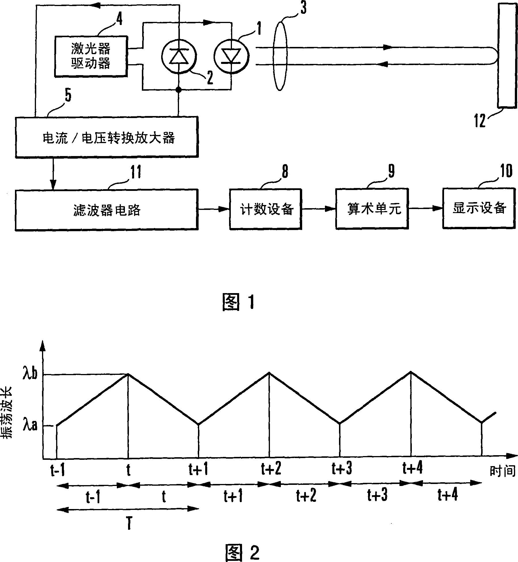
[0045] The present invention is a technique for measuring distance based on an interference signal between emitted waves and waves reflected by an object when sensing using wavelength modulation. Therefore, this technique can be applied to optical interferometers other than self-mixing type interferometers and interferometers other than optical interferometers. The case of self-mixing using a semiconductor laser will be described in detail below. When the oscillation wavelength of the semiconductor laser is changed while applying the laser beam from the laser to the measurement target, the displacement of the measurement target is reflected in the number of MHPs while the oscillation wavelength is changed from the minimum oscillation wavelength to the maximum oscillation wavelength (or, from the maximum oscillation wavelength wavelength changes to the minimum oscillation wavelength). Therefore, by checking the number of MHPs when the oscillation wavelength is changed, the sta...

no. 2 example

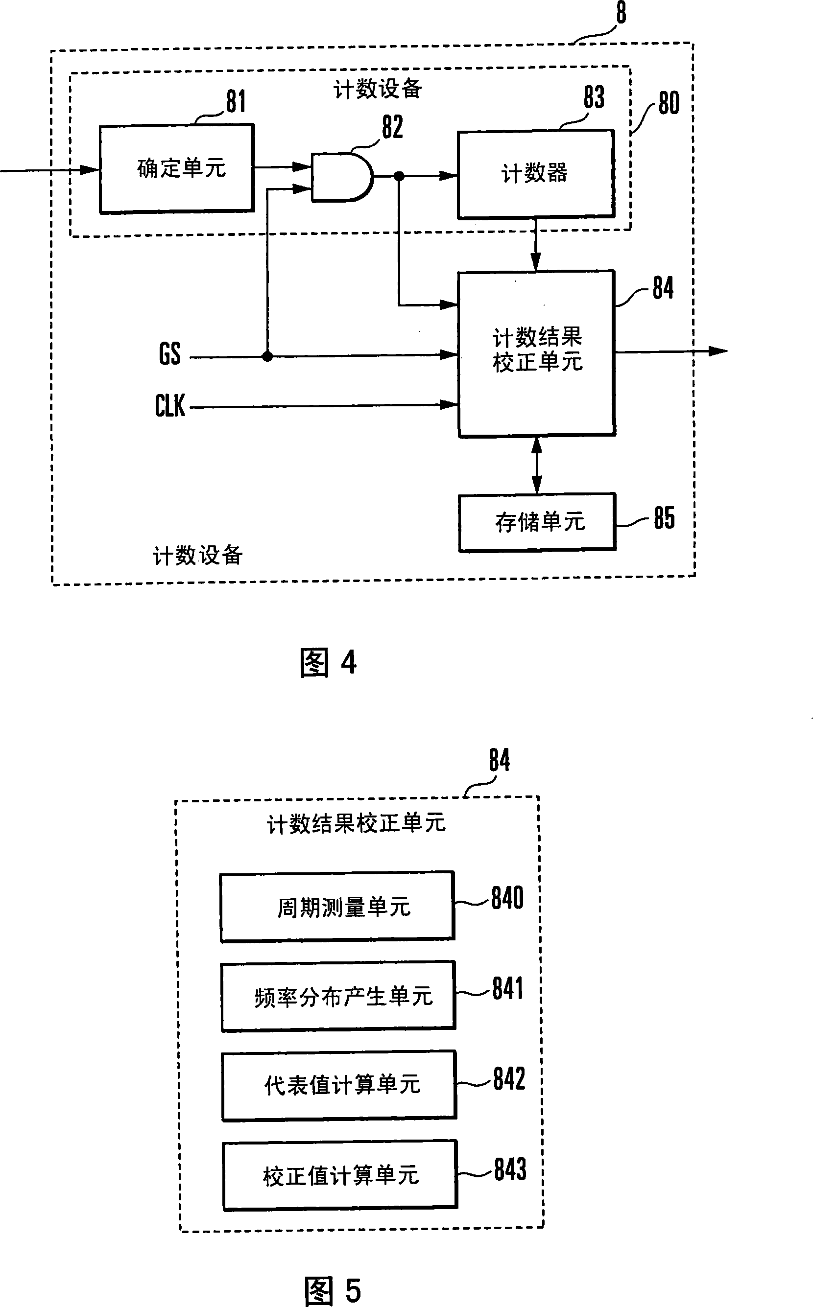
[0134] Next, a second embodiment of the present invention will be described. In the first embodiment, the count result is corrected by using the median value as a representative value of the MHP cycle. However, it is also possible to use the mode number as a representative value of the period.

[0135] Assume that the frequency distribution of the MHP cycle is shifted from the correct distribution j shown in FIG. 21 to the distribution k shown in FIG. 21 . In this case also the median value of the MHP period is shifted from the correct value T0 to the value Td. In this case, if the count result is corrected using the median value Td, the error in the corrected count result increases.

[0136] Therefore, if the influence of the shift of the frequency distribution due to the noise component is conceivable, the mode is used as a representative value of the period. More specifically, the representative value calculation unit 842 of the count result correction unit 84 calculates...

no. 3 example

[0146] In the first and second embodiments, the MHP waveform is extracted from the output signal of the photodiode 2 . The photodiode 2 serves as a light receiving device that converts the light output of the semiconductor laser 1 into an electric signal. However, the MHP waveform can be extracted without using the photodiode 2. FIG. 22 shows the configuration of a distance meter according to a third embodiment of the present invention. The same reference numerals as in FIG. 1 denote the same elements in FIG. 22 . The distance meter in this embodiment uses a voltage detection circuit (signal acquisition device) 13 instead of the photodiode 2 and voltage / current conversion amplifier 5 in the first embodiment.

[0147] The voltage detection circuit 13 detects and amplifies the voltage between the terminals of the semiconductor laser 1 , that is, the voltage between the anode and the cathode. When interference is caused by the self-mixing effect between the laser beam emitted ...


PUM


Abstract

A counting device includes a counting unit, period measuring unit, frequency distribution generating unit, representative value calculation unit, and correction value calculation unit. The counting unit counts the number of signals input during a counting interval. The number of signals has a linear relationship with a physical quantity. The signals have a substantially single frequency when the physical quantity is constant. The period measuring unit measures the period of a signal every time a signal is input during the counting interval. The frequency distribution generating unit generates the frequency distribution of signal periods from the measurement result. The representative value calculation unit calculates the representative value of the distribution of periods of signals from the frequency distribution. The correction value calculation unit obtains a total sum Ns of frequencies in a class not more than a first predetermined multiple of the representative value calculated and a total sum Nw of frequencies in a class not less than a second predetermined multiple of the representative value from the frequency distribution, and corrects the count result on the basis of the frequencies Ns and Nw.

Description

technical field [0001] The present invention relates to a counting device that counts the number of signals, and a distance meter for obtaining a distance to a measurement target, wherein the number of interference waveforms is measured according to the distance by using the counting device. Background technique [0002] Since non-contact measurement is used, distance measurement using lasers that interfere with light does not interfere with the measurement target, and thus has long been used as a high-precision measurement method. Recently, attempts have been made to miniaturize devices using semiconductor lasers as light measurement light sources. A typical example of such a device is the use of an FM heterodyne interferometer. This device can measure a relatively long distance with high accuracy, but has the disadvantage that the optical system is complicated due to the use of an interferometer outside the semiconductor laser. [0003] In contrast to this, there is prop...

Claims


Application Information

Patent Timeline
Patent Type & Authority Applications(China)
IPC IPC(8): G01C3/00G01B11/02
Inventor 上野达也
Owner YAMATAKE HONEYWELL CO LTD
Why Eureka
Try Eureka