Layer-twisted type optical-cable

A layered, optical cable technology, applied in the direction of fiber mechanical structure, etc., can solve the problems of increasing the diameter of the optical cable, increasing the cost, and poor strength of the loose tube, and achieving weight reduction, cost saving, strong lateral pressure resistance and load-bearing capacity. Effect

Inactive Publication Date: 2008-07-30
SHENZHEN SDG INFORMATION CO LTD
View PDF0 Cites 13 Cited by
  • Summary
  • Abstract
  • Description
  • Claims
  • Application Information

AI Technical Summary

Problems solved by technology

[0008] 1. In the prior art, the material of the loose tube in the optical fiber production process is polybutylene terephthalate PBT, polypropylene PP, polyurethane PA, polycarbonate PC or other polymers, etc. These are some expansion ratios Higher materials, the optical cables produced by using it will cause engineering accidents due to relatively severe thermal expansion and contraction, and are not suitable for use in extreme weather conditions such as high cold, high heat, or large temperature differences.
[0009] 2. Due to the poor strength of the loose tube made of the above materials, it is not enough to support the weight of the cable itself and the pressure during the laying construction process. Therefore, there must be a strengthening core in the center of the cable, and iron and aluminum in the jacket. With woven armor, this increases the weight per unit length of the optical cable, and also increases the caliber of the optical cable, which increases the pipe occupied by the optical cable with the same capacity when it is laid, and increases the cost.

Method used


Image

  • Layer-twisted type optical-cable
  • Layer-twisted type optical-cable

Examples


Embodiment Construction

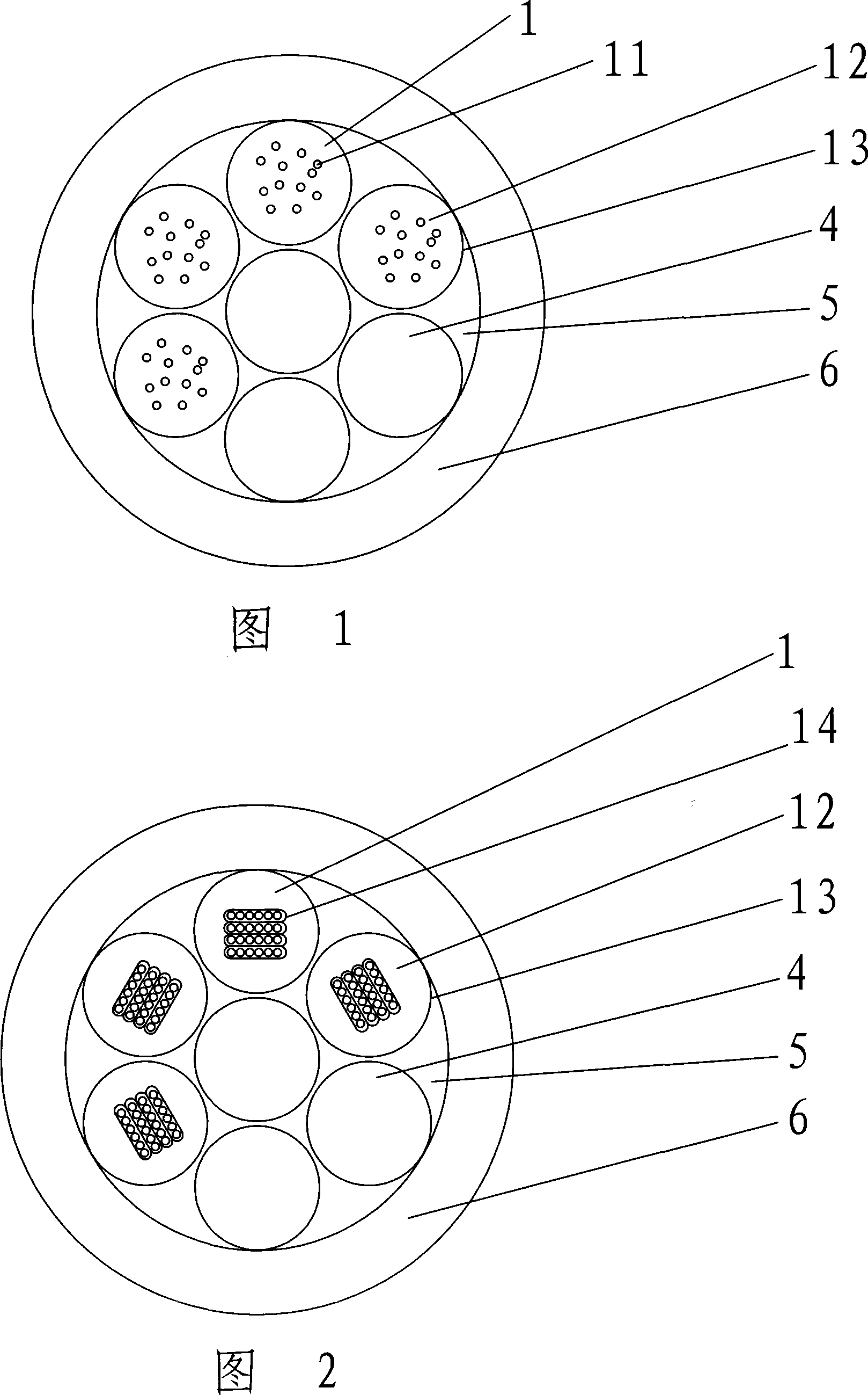
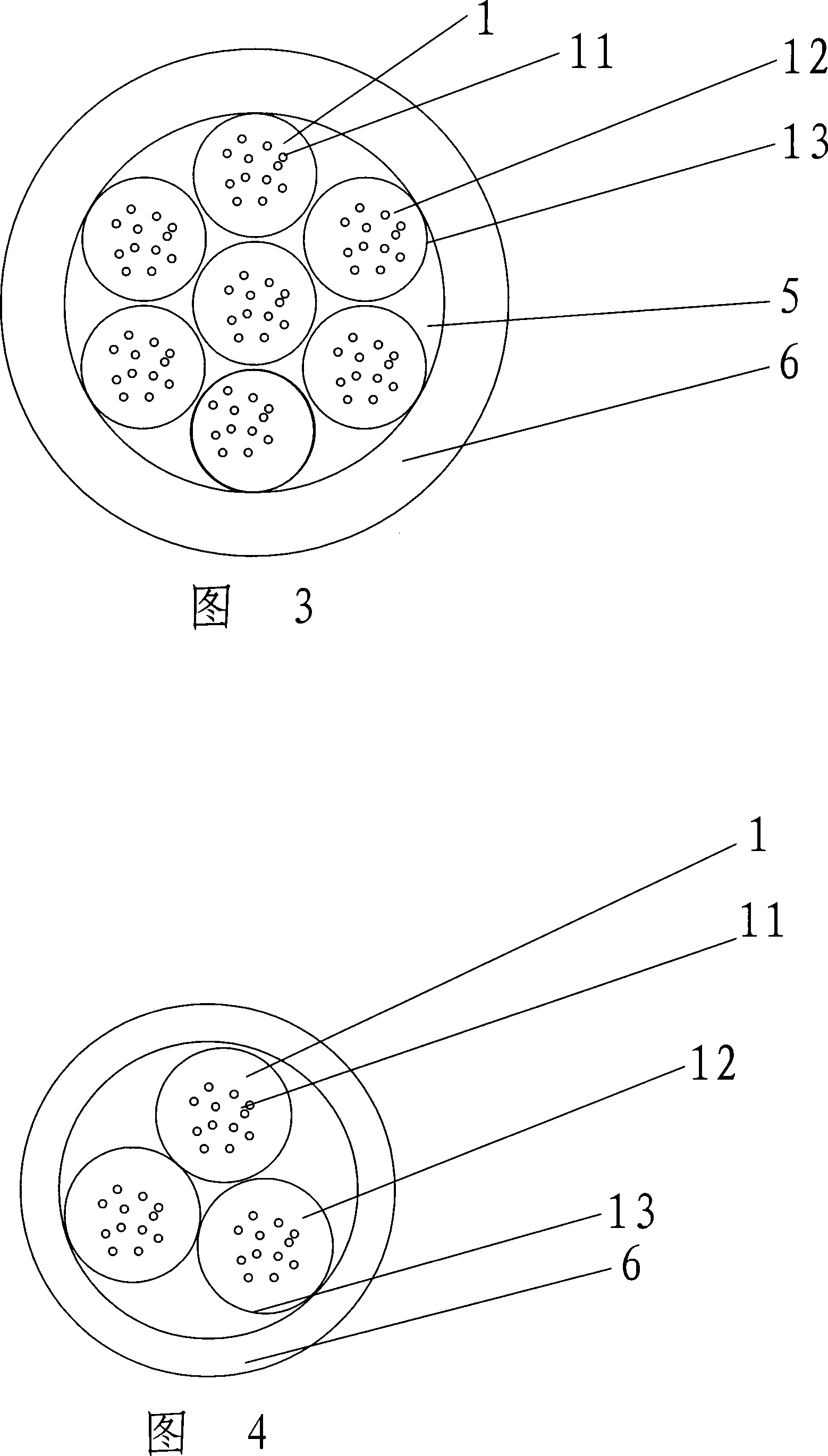
[0023] Fig. 1 is a cross-sectional view of Embodiment 1 of the present invention, as shown in the figure, the outside of the optical cable is a sheath 6, where the sheath 6 of the optical cable is made of polyethylene or other materials, and its main function is to wrap the cable core inside, The cable core is formed by twisting four optical cable core wires 1 and two steel wires 4 around a steel wire in the center. According to requirements, the number of optical cable core wires and steel wires in the cable core can be different. The optical cable core wire 1 is composed of a sleeve 13 made of a plurality of optical fibers 11 and a stainless steel tube for protecting the optical fiber. The diameter of the standard optical fiber is only a few hundred microns, so multiple optical fibers can be placed in one stainless steel tube. , fiber grease 12 is also filled between the gaps of the optical fibers in each stainless steel tube in order to better protect the optical fibers. At...


PUM


Abstract

The invention discloses a layer stranded optical cable, which is suitable for being used under extreme climatic conditions such as high cold weather, high hot weather, high temperature difference weather, etc., and has relatively small cross sectional area. The technical proposal is that the layer stranded optical cable comprises a cable core and a protective cover surrounding the cable core, wherein the cable core is twisted by at least two optic cable core wires, which are prepared by wrapping optical fiber with a metal sleeve. The invention replaces the non-metal sleeve in the prior art with the metal sleeve, so that the optic cable core wire has higher side pressure resistant performance, the sleeve of the optical fiber cable is not armored by the steel strip or aluminum strip at the inner side or outer side thereof, the center of the optical fiber cable has no need to bear heavy reinforced core, and the outside diameter of the optical fiber is remarkably reduced. Furthermore, because of the relatively low expansion coefficient of the metal sleeve, the invention solves the engineering problem arising from relatively severe thermal expansion and contraction of common loose tube layer stranded optical cable in regions with high cold weather, high hot weather or high temperature difference weather.

Description

technical field [0001] The invention relates to the technical field of optical cable manufacturing, in particular to a layer-stranded optical cable suitable for use in extreme climate conditions such as high cold, high heat, or large temperature difference changes. Background technique [0002] With the advent of the information age, the amount of information transmitted has exploded. As an effective means of large-capacity, long-distance transmission, fiber optic cables have been widely used. The application of optical cable is also gradually developing from long-distance trunk line to metropolitan area network and access network. The development of the industry promotes the progress of technology, new cable structures are constantly introduced, and new technologies are constantly being applied. With the wide application of optical cable communication, the requirements for information transmission media in some special occasions are also getting higher and higher. [000...

Claims


Application Information

Patent Timeline
Patent Type & Authority Applications(China)
IPC IPC(8): G02B6/44
Inventor 张伟民王爱国王晓锋王华斌陈焕新
Owner SHENZHEN SDG INFORMATION CO LTD
Why Eureka
Try Eureka