Electromagnetic relay resistant to electric repulsive force

A technology of electromagnetic relay and electric repulsion, which is applied in the direction of electromagnetic relay, electromagnetic relay details, relays, etc., can solve the problems of electric repulsion damage, easy bounce of contacts, strong arc generation, etc., and achieve the balance of suction and reaction force and electrical contact Reliable, the effect of resisting short-circuit current

Inactive Publication Date: 2008-07-30
XIAMEN HONGFA ELECTRIC POWER CONTROLS
View PDF0 Cites 44 Cited by
  • Summary
  • Abstract
  • Description
  • Claims
  • Application Information

AI Technical Summary

Problems solved by technology

The electrodynamic repulsion formed by the short-circuit current is always in the opposite direction of the contact closure, and the force that promotes the contact closure is only the force of the adjustment of the electromagnetic system, which is not enough to resist the electrodynamic repulsion, and the contacts are easy to bounce back and generate a strong arc. , the contacts are melted and burned due to the instantaneous high temperature, so the electric repulsion has a great destructive effect

Method used


Image

  • Electromagnetic relay resistant to electric repulsive force
  • Electromagnetic relay resistant to electric repulsive force
  • Electromagnetic relay resistant to electric repulsive force

Examples


Embodiment Construction

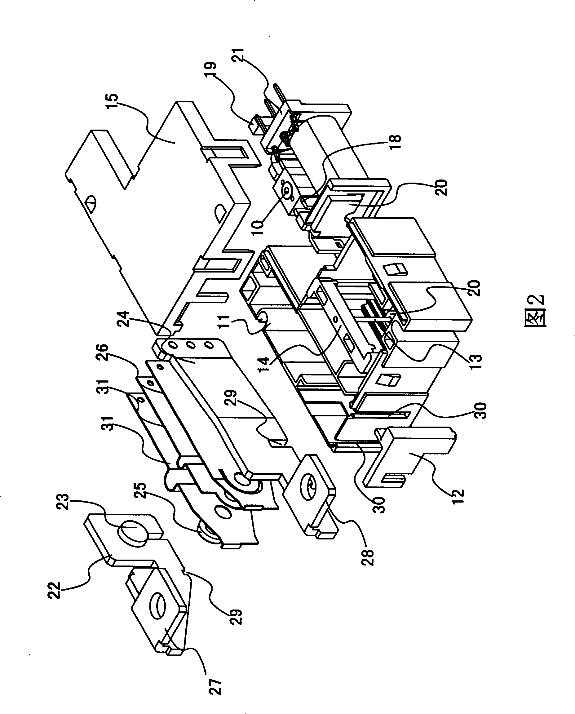
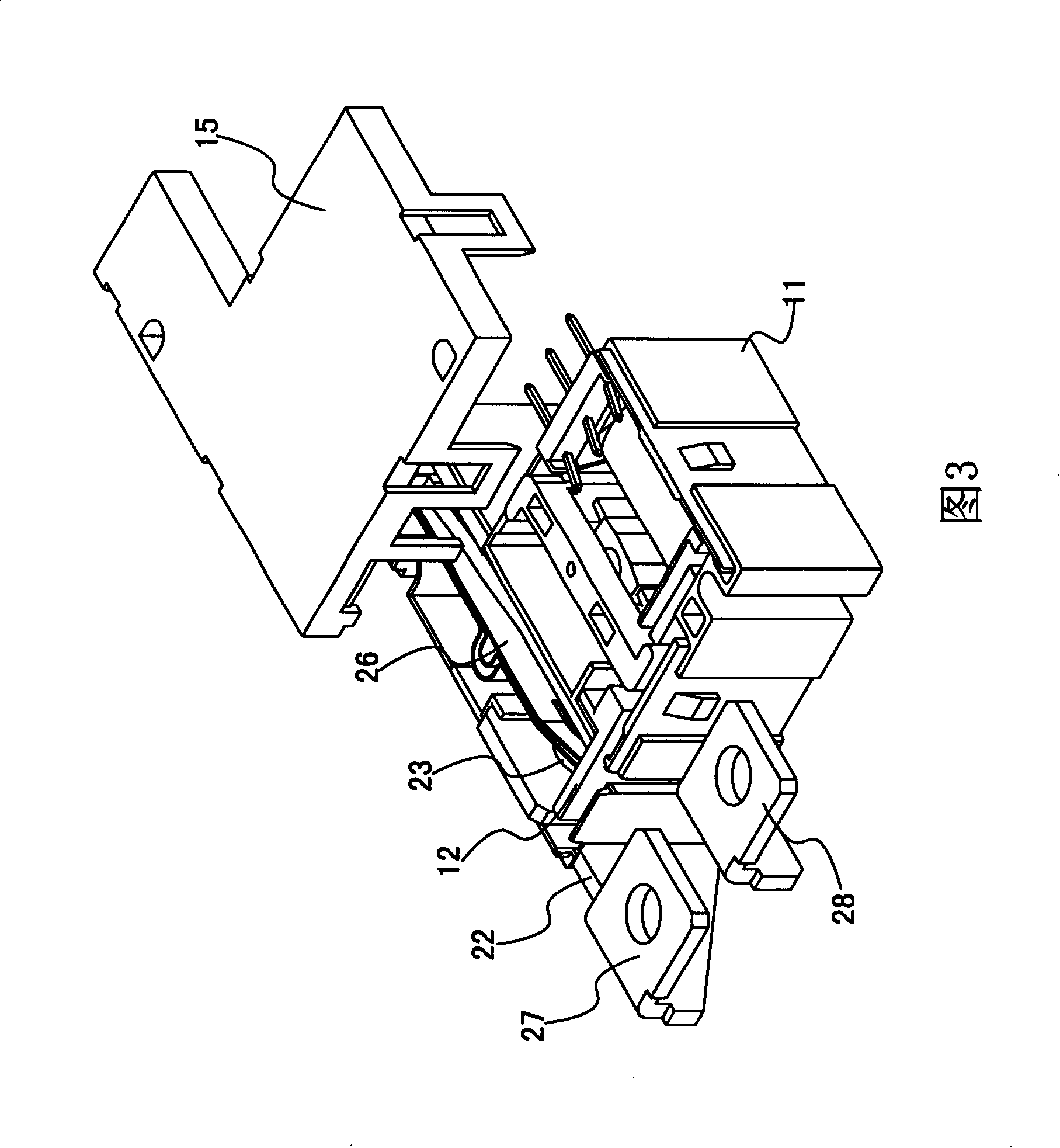
[0026] Please refer to FIG. 2 , an electromagnetic relay resisting electrodynamic repulsion, which has a contact system, an electromagnetic system 10 , a base 11 , a push card 12 , a shaft 13 , a fixing frame 14 and a housing 15 .

[0027] Please refer to Figure 2, Figure 3, Figure 5 as well as Image 6 , the above-mentioned base 11 is provided with a reverse buckle 16, and the above-mentioned shell 15 is provided with a reverse buckle 17, and the shell 15 and the base 11 are assembled together through the phase-tight buckle between the reverse buckle 16 and the reverse buckle 17 . In this embodiment, the assembling method adopts the reverse interlocking method, but it is not limited thereto, and other assembling methods should also fall within the protection scope of the present invention.

[0028] Please refer to Fig. 2, the fixed frame 14 is installed in the base 11; the electromagnetic system 10 includes an armature 18, a permanent magnet 19, a yoke 20 and a coil frame ...


PUM


Abstract

The invention discloses an electromagnetic relay which resists electric repulsion force. When a relay contact is closed and the electromagnetic relay works, the relay is loaded, and a coil is provided with a setting signal. The current direction of a second leading-out sheet is opposite to the current direction of a movable spring, thus producing a magnetic field through the interaction. The magnetic field enables the movable spring to produce electromagnetic force. The produced electromagnetic force is in the same direction as the pushing force produced by a pushing card, thus increasing the contact pressure of a contact which is enough to resist the destruction of the electric repulsion force. The invention completely eliminates the technical problem that the electric repulsion force causes the contact to return easily in prior art. The invention further has the advantages of large resultant force of the electromagnetic force and the pushing force, small contact pressure of the contact, small contact resistance, reliable and stable electrical contact of the contact, capability of resisting short-circuit current, preventing the functional relay from being damaged, large switching power of the contact, capability of working under large load for long term, compact conformation, shock resistance, high impact capability, high capability of carrying load, low price, high manufacturability. In addition, the switching frequency of the invention shall not be too high, and the invention is applicable for streamlined production in large quantity.

Description

technical field [0001] The invention relates to an electromagnetic relay, in particular to an electromagnetic relay resisting electrodynamic repulsion. Background technique [0002] As an electromechanical component, electromagnetic relays are widely used in power control, industrial automation devices and household appliances. The existing magnetic latching relay generally includes a contact system, an electromagnetic system, a push card, a fixing frame, a base and a casing. The development trend of electromagnetic relays is low power consumption, miniaturization and large load, and permanent magnets are used in existing electromagnetic systems. The working principle of the relay with permanent magnet steel is: the open and closed state of the contact is usually maintained by the magnetic force generated by the permanent magnet steel. , The anti-DC pulse signal excites the coil, and the relay completes the state transition between open and closed in an instant, and then t...

Claims


Application Information

Patent Timeline
Patent Type & Authority Applications(China)
IPC IPC(8): H01H51/01H01H50/54H01H50/58H01H50/16
Inventor 冯邦永
Owner XIAMEN HONGFA ELECTRIC POWER CONTROLS
Why Eureka
Try Eureka