Eureka AIR delivers breakthrough ideas for toughest innovation challenges, trusted by R&D personnel around the world.

Battery cover plate with new type structure and secondary battery thereof

A technology of battery cover and new structure, applied in secondary battery manufacturing, structural parts, battery pack components and other directions, can solve the problems of unstable sealing, inconvenient external connection, reducing battery volume specific capacity, etc. Tightness and safety, flexible external connection and disassembly, and the effect of improving volumetric capacity

Inactive Publication Date: 2008-07-30
HYB BATTERY
View PDF0 Cites 17 Cited by
  • Summary
  • Abstract
  • Description
  • Claims
  • Application Information

AI Technical Summary

Problems solved by technology

The disadvantage of this structure is that the sealing part and the connecting force part are integrated, so that when the upper nut is screwed to connect with the external conductor, the lower sealing nut is often loosened and leaks, and the lower nut of this structure occupies too much space inside the battery. Large, reducing the volume specific capacity of the battery
While the traditional structure 2 (as attached Figure 4-6 ) of the battery cover plate, the positive and negative electrode connectors are electrode pressure plates with at least two fixing holes. The advantage of this structure is that the sealing parts and the electrode connection stress parts are separated from each other, and the battery is stored or in motion. Under the circumstances, the electrode connectors are not easy to loose and leak, and the volume specific capacity of the battery can be increased, but the disadvantage of this structure is that the battery must be connected to the external conductor by wire welding, which makes it difficult to maintain, disassemble and externally connect.
The external connection and disassembly process is very destructive to the battery, and for the battery pack, due to the difficulty of connection and disassembly, often one of the batteries has a problem and the entire battery pack is scrapped
[0006] All in all, the traditional structure of the battery cover and its positive and negative electrode connectors has disadvantages such as unstable sealing, inconvenient external connection, and inconvenient use, and it is difficult to adapt to the growing needs of industrial or civil fields.

Method used


Image

  • Battery cover plate with new type structure and secondary battery thereof
  • Battery cover plate with new type structure and secondary battery thereof
  • Battery cover plate with new type structure and secondary battery thereof

Examples


Embodiment 1

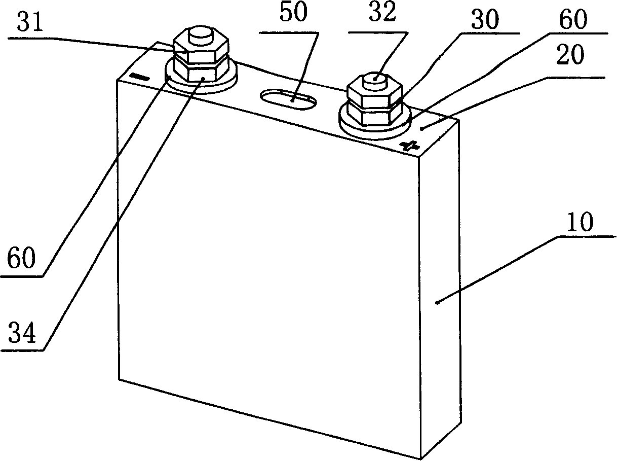
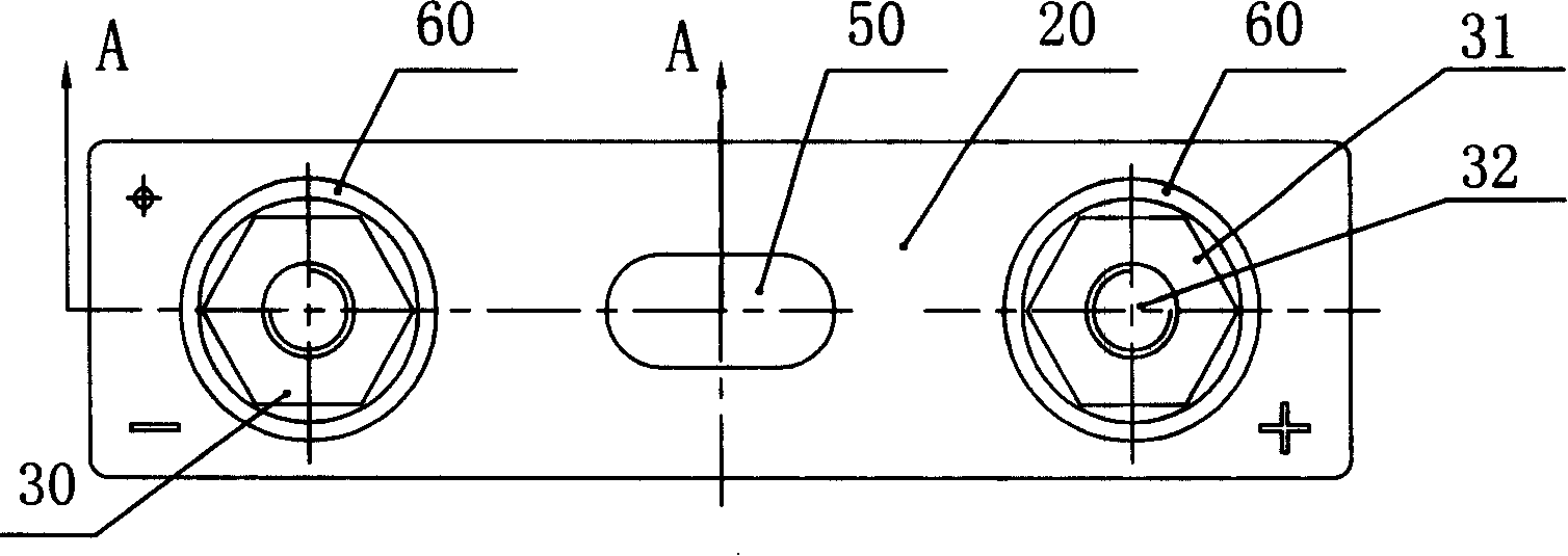
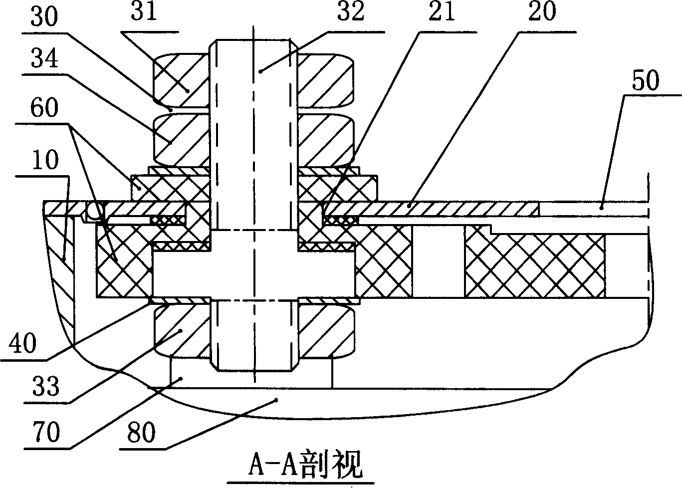
[0035] Such as Figure 7-9 , shown in order are the three-dimensional, top view and partial cross-sectional schematic diagrams of the secondary battery embodiment 1 of the present invention. The secondary battery includes a metal case 10, a battery cover plate, and the battery cover plate includes a plate body 20 with a through hole 21, a positive / negative electrode connector 30, a positive / negative conductive sheet 40, an explosion-proof device 50, and a lining on the through hole 21. The insulating washer 60 at the hole, the positive / negative electrode connectors 30 are respectively fixed on the plate body 20 by respective fasteners 35 and insulating washer 60, and the positive / negative conductive strips 40 are respectively connected to respective electrodes by the fasteners 35 The parts 30 are connected and fixed under the insulating washer 60 , the lower ends of the positive and negative conductive sheets 40 are respectively connected to the positive and negative tabs 70 ,...

Embodiment 2

[0039] Such as Figure 10 , 11 , shown in sequence are the top view and cross-sectional schematic diagrams of the battery cover plate in Example 2 of the present invention; Figure 12 , 13 It is a top view and a schematic cross-sectional view of the main body of the electrode pressure plate in Embodiment 2 of the present invention in sequence. The battery cover plate includes a plate body 20 with a through hole 21, a positive / negative electrode connector 30, a positive / negative conductive sheet 40, an explosion-proof device 50, an insulating gasket 60 lining the through hole 21, and a positive / negative electrode connection. Components 30 are respectively fixed on the plate body 20 through respective insulating washers 60, positive / negative conductive strips 40 are respectively connected with respective electrode connectors 30 through fasteners 35 and fixed under the insulating washers 60, and the electrodes are connected Part 30 includes fastener solid rivet 35 and electrod...

Embodiment 3

[0044] Such as Figure 14-15 , shown in sequence are the top view and cross-sectional schematic diagrams of the battery cover plate of Example 3 of the present invention; Figure 16-19 , which are the top view and cross-sectional view of the electrode pressure plate and the threaded connector in the third embodiment of the present invention. It can be seen from the above figure that the other structures are the same as in Embodiment 2 except that the threaded connectors on the electrode pressure plate 36 are lag bolts 390 and hex nuts 391 passing through the plate opening 361 .


PUM


Abstract

The invention relates to a battery cover plate with novel structure and a secondary battery thereof. The battery cover plate comprises a plate body with via-holes, positive / negative electrode connectors, positive / negative conductive sheets, an anti-explosion device and insulating gaskets arranged on the via-holes, wherein the positive / negative electrode connectors are respectively fixed on the plate body through respective insulating gaskets; the positive / negative conductive sheets are respectively connected with each electrode connector and fixed below the insulating gaskets; the electrode connector comprises two or more fasteners, an electrode press plate with fixing holes identical to the fasteners in number, and screw-thread connectors arranged on the electrode press plate for conductive connection; the via-holes on the plate body correspond to the fixing holes on the electrode press plate; and the fasteners penetrate through the via-holes and the fixing holes to fix the electrode press plate on the plate body. The battery cover plate and the positive / negative electrode connectors on the secondary battery of the invention have more stable sealing performance, more flexible external connection, maintenance and disassembly and more convenient usage.

Description

technical field [0001] The present invention relates to a chemical power source, and more specifically, the present invention relates to a secondary battery and battery components thereof. Background technique [0002] With the rapid development of digital products such as digital cameras, video cameras, notebook computers, and mobile DVDs, secondary batteries with high specific capacity, high energy density, and multiple charge and discharge capabilities have been widely used. At the same time, due to the development of electric vehicles, electric bicycles, and hybrid electric vehicle industries, secondary power batteries are attracting more and more attention. In more occasions, the power battery must be used by multiple batteries in series and parallel to increase the output voltage and capacity. Therefore, with the continuous improvement of secondary battery technology, higher requirements are put forward for the series and parallel combination of batteries. . [0003]...

Claims


Application Information

Patent Timeline
Patent Type & Authority Applications(China)
IPC IPC(8): H01M2/04H01M2/06H01M10/04H01M50/147H01M50/172
CPCY02E60/10Y02P70/50
Inventor 江强郑为工梁奇孟亚斌李小伟
Owner HYB BATTERY
Why Eureka
Eureka Blog
Learn More