

Millimeter wave miniaturized multichannel transmitting-receiving subassembly and its phase compensation process
A transceiver component and phase compensation technology, applied in radio wave measurement systems, instruments, etc., can solve the problems of unguaranteed phase consistency, poor phase modulation accuracy, and no implementation method, etc., so that the phase compensation method is simple and easy to operate, and improves the effectiveness Radiation gain, effect of improving power combining efficiency
- Summary
- Abstract
- Description
- Claims
- Application Information
AI Technical Summary
Problems solved by technology
Method used
Image

Examples
Embodiment 1
[0047] Taking the phase error of the transmission channel as an example of 95 degrees to introduce the operation steps of the phase error compensation of the transceiver component proposed by the present invention:
[0048] 1. According to the requirements of the radar device, it is estimated that the phase relationship between the transmission channels is zero degrees;
[0049] 2. Use a vector network analyzer to measure the phase error of the transmit channel, and obtain the phase error θ between the two transmit channels of the transceiver component when the operating frequency is 33GHz 1 is 95 degrees.
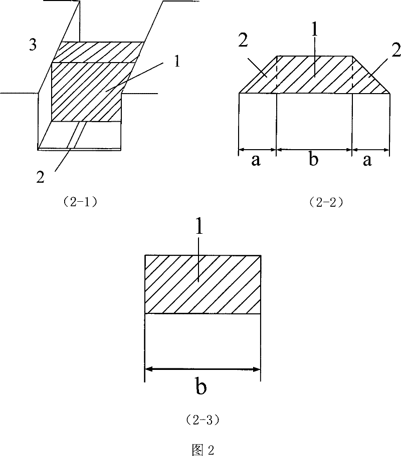
[0050] 3. Choose a regular cuboid ceramic medium to load, the thickness is 0.5mm, the width is equal to the shielding cavity and the side wall is in full contact with the metal side wall of the shielding cavity. The height of the air shielding cavity is 3 mm, which is convenient for calculation and selection of a cuboid structure without transition section . At this time...
Embodiment 2
[0057] Taking the phase error of the transmission channel as 50 degrees as an example to introduce the phase error compensation operation steps of the transceiver component proposed by the present invention, the specific operation steps are the same as those in Embodiment 1, except that the length of the compensation section is different. Suppose the phase error θ 2 λ is 50 degrees and the operating frequency is 33GHz 0 9.09 mm, equivalent dielectric constant ε re is 1.583, and these known parameters are substituted into formula (1) to get
[0058] (4)
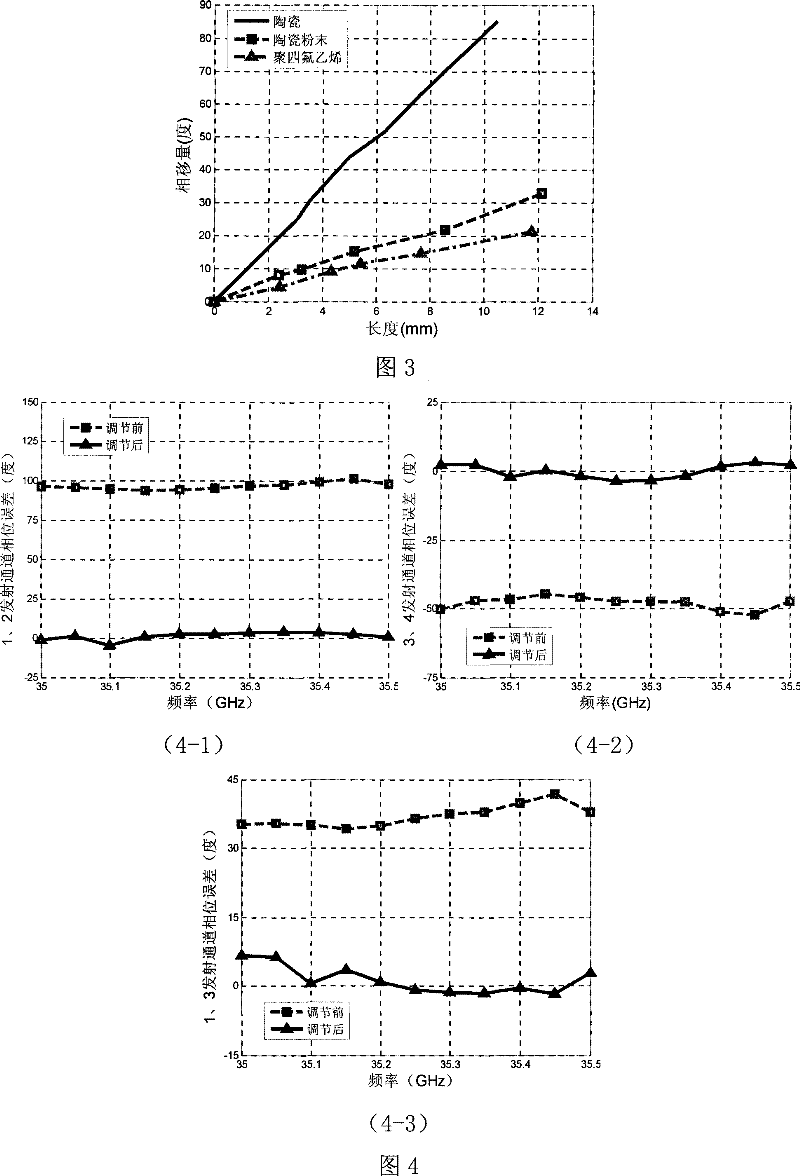
[0059] Perform phase compensation according to the operation steps in Embodiment 1, Figure 4-2 It is the actual measurement result of the phase error before and after compensation using the medium-loaded microstrip line method proposed by the present invention when the channel phase error is 50 degrees. After compensation, the phase error of the channel with an operating frequency of 33 GHz is 2.21 degrees.
Embodiment 3
[0061] Taking the phase error of the transmission channel as 35 degrees as an example to introduce the phase error compensation operation steps of the transceiver component proposed by the present invention, the specific operation steps are the same as those in Embodiment 1, except that the length of the compensation section is different. Suppose the phase error θ 3 is 35 degrees, when the operating frequency is 33GHz λ 0 is 8.57 mm, the equivalent dielectric constant ε re is 1.583, and these known parameters are substituted into formula (1) to get
[0062] (5)
[0063] Perform phase compensation according to the operation steps in Embodiment 1, Figure 4-3 It is the actual measurement result of the phase error before and after compensation by using the medium-loaded microstrip line method proposed by the present invention when the channel phase error is 35 degrees. After compensation, the phase error of the channel with an operating frequency of 33 GHz is 4.57 degrees. ...
PUM
 Abstract
Description
Claims
Application Information