Humidifying pad

A surface layer and heating element technology, applied in the field of humidification pads, can solve the problems of speeding up the temperature rise, prolonging the temperature duration, not revealing, etc., to achieve the effect of rapid heating and humidification

Inactive Publication Date: 2008-08-06
UNI CHARM CORP
View PDF1 Cites 2 Cited by
  • Summary
  • Abstract
  • Description
  • Claims
  • Application Information

AI Technical Summary

Problems solved by technology

However, in Patent Documents 1 and 2, measures to speed up the temperature rise rate and measures to prolong the temperature duration are not disclosed.

Method used


Image

  • Humidifying pad
  • Humidifying pad
  • Humidifying pad

Examples


Embodiment 1

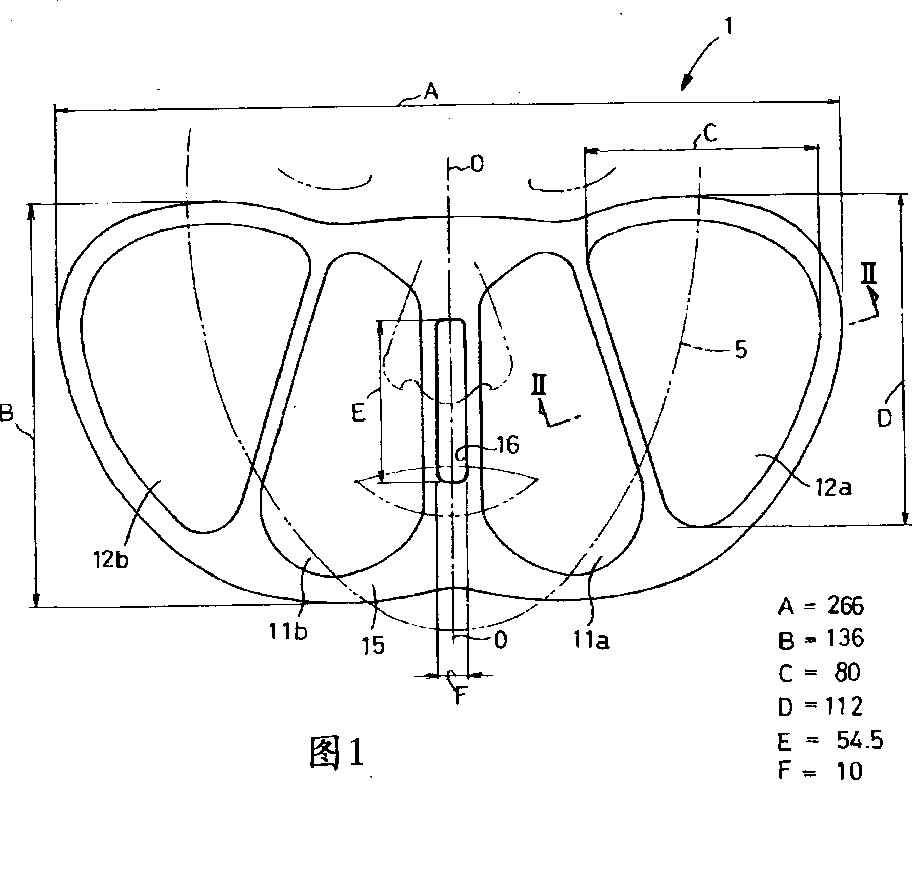
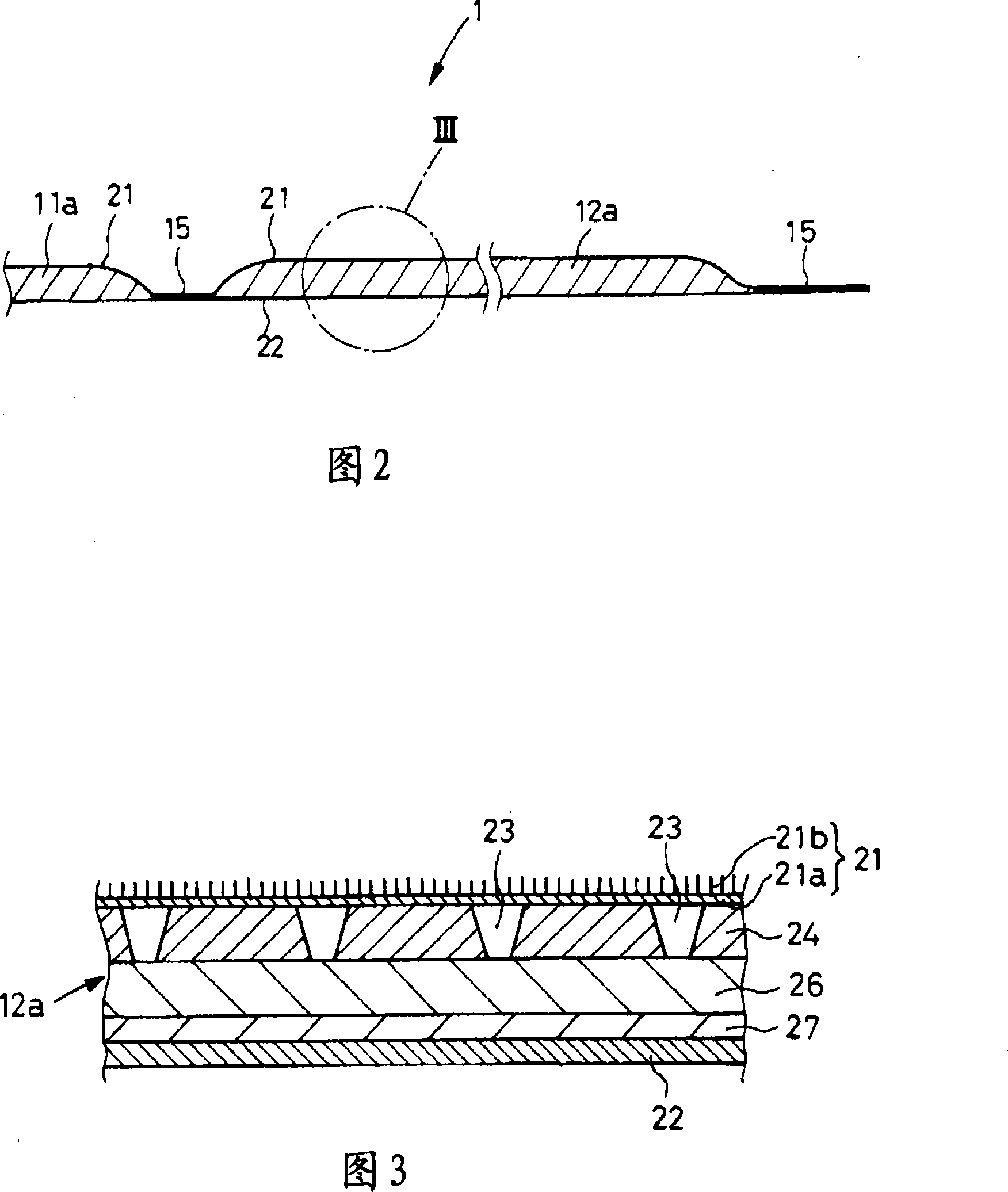
[0028] Adopt the pad 1 of Fig. 1 shape, be 80mm with dimension C, be 112mm with dimension D, the area of ​​the first surface layer 21 is 45.4cm 2 The right outer humidifier 12a is used as an object, and the characteristics of the humidifier are evaluated. The humidifying part 12a has a cross-sectional structure as shown in FIG. 2 , Flocking non-woven fabric with a thickness of 1.5-2.5mm. The temperature regulating layer 24 is to use a weight per unit area of ​​73g / m 21. The thickness is 3 mm, the expansion ratio is 30 times, and the opening ratio of the through hole 23 is 30% of the foamed polyethylene cloth under the layer 24 . The heating element 26 in the heating part 12a, in addition to iron powder containing 95% by weight, the remaining 5% by weight is the base material of leech powder and wood powder as a water-retaining material, and activated carbon as an oxidation accelerator of 5% by weight. and saline with a salt concentration of 20% by weight. The impregnation ...


PUM


Abstract

The present invention improves the humidification pad used on the skin so that its temperature rises quickly and can maintain the required temperature for a long time. A humidification pad (1) has a heating element (26) between the first and second surface layers (21, 22). The heating element (26) contains metal powder, salts and water, and when oxygen is supplied through the air-permeable first surface layer (21), oxidation heat is generated to turn the water into steam. As the salt and water, the heating element (26) is impregnated with 17.5 to 26% by weight of salt water having a salt concentration of 18 to 22% by weight.

Description

technical field [0001] The present invention relates to a humidifying pad capable of supplying water vapor at an appropriate temperature to the skin of the face or other parts. Background technique [0002] Conventionally, humidifying pads that can be applied to the skin such as the face and supply water vapor to the skin are known. For example, Patent Document 1 discloses a water vapor generator as such a pad. The water vapor generating body is formed by wrapping the heating element containing metal powder, salt and water with a moisture-permeable thin layer material, which can generate 0.01mg / cm 2 ·Min above water vapor, the temperature of the water vapor is controlled below 50°C. In addition, the pad disclosed in Patent Document 2 has deformability suitable for use on the face. [0003] Patent Document 1: Japanese Patent No. 3049707 [0004] Patent Document 2: Japanese Patent Laid-Open No. 2004-358110 [0005] When a humidifying pad is applied to the face, etc., in a...

Claims


Application Information

Patent Timeline
Patent Type & Authority Applications(China)
IPC IPC(8): A61F7/00A61F7/08A45D44/22
CPCA61F7/03A61F7/032A61F7/034A61F2007/0003A61F2007/0062
Inventor 宫泽清竹内直人寺冈裕美花尻武
Owner UNI CHARM CORP
Why Eureka
Try Eureka