Hydraulic shock absorber

一种液压缓冲器、贮液器的技术,应用在液压缓冲器领域,能够解决环状部件变形、密封性下降、异物混入等问题,达到减轻压力、减少尺寸、简化装配的效果

Active Publication Date: 2008-08-13
HITACHI LTD
View PDF7 Cites 6 Cited by
  • Summary
  • Abstract
  • Description
  • Claims
  • Application Information

AI Technical Summary

Problems solved by technology

Since the oil tank is fixed by welding the ring-shaped member for holding the inner tank (brada), which divides the oil chamber and air chamber of the reservoir, there is a possibility that foreign matter may be mixed in due to spatter generated during welding In addition, the ring part may be deformed and the sealing performance may be reduced due to the heat during welding.

Method used


Image

  • Hydraulic shock absorber
  • Hydraulic shock absorber
  • Hydraulic shock absorber

Examples


Embodiment Construction

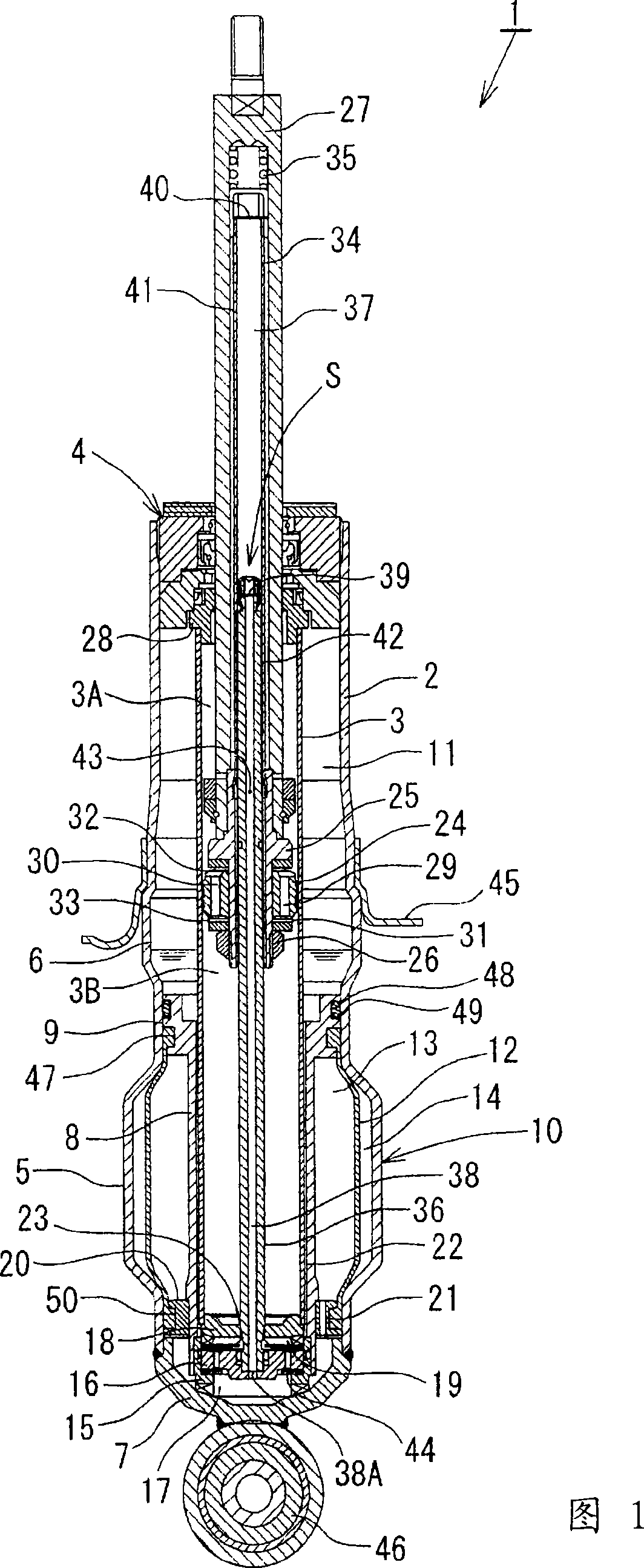
[0023] An embodiment of the present invention will be described in detail below according to the accompanying drawings.

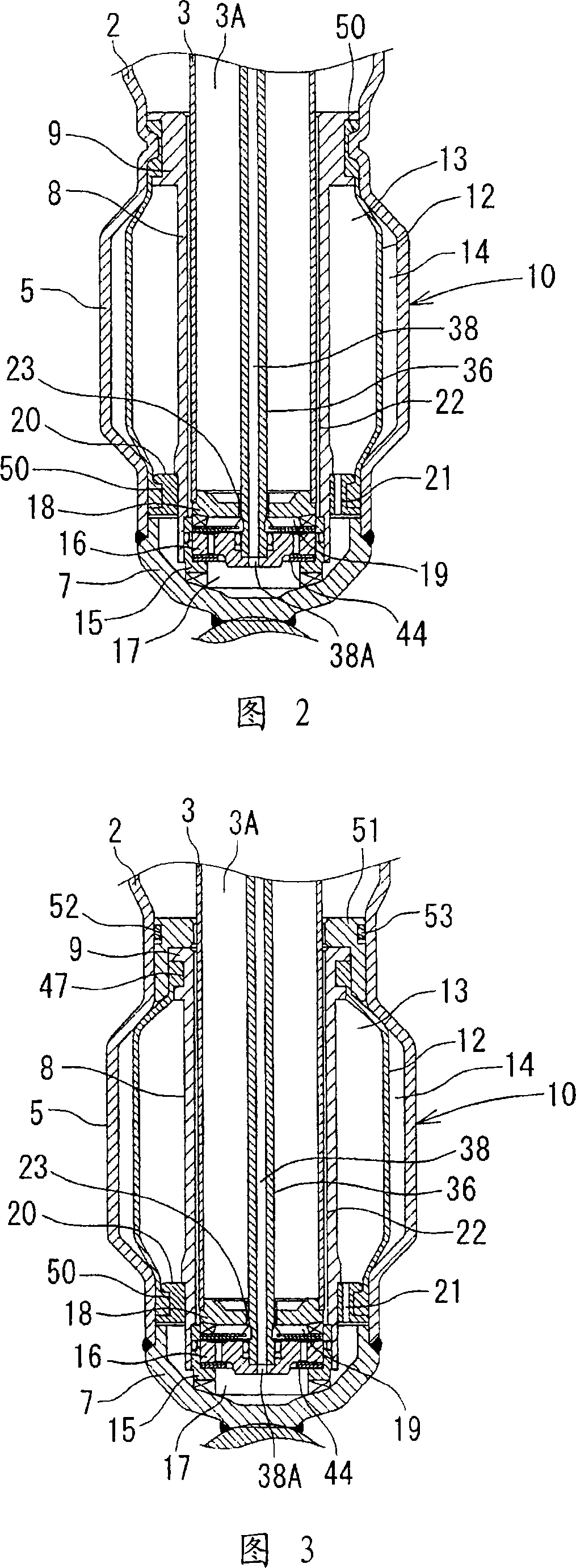
[0024] As shown in FIG. 1 , the hydraulic shock absorber 1 has a double-cylinder structure in which a cylinder 3 is inserted into a substantially bottomed cylindrical casing 2 (outer cylinder). The sealing member 4 is attached to the opening of the casing 2 to form an annular chamber between the casing 2 and the cylinder 3 . In the case 2, the lower end portion side is expanded by bulging processing or the like, and the expanded diameter portion 5 is formed. The upper portion of the diameter-expanding portion 5 is slightly enlarged in diameter to form the spring holder support portion 6 . The cover member 7 is welded to the bottom of the casing 2 to block the bottom of the casing 2 . The partition member 8 is inserted between the enlarged diameter portion 5 of the casing 2 and the cylinder 3, and the outer flange portion 9 formed on the upper end of the p...


PUM


Abstract

The invention relates to a hydraulic shock absorber. A piston (24) connected with a piston rod (27) is fitted in a cylinder (3) having a hydraulic fluid sealed therein. A damping force is generated through extension (31) and compression disk valves (32) and an orifice (33). Vehicle height adjustment is performed with a self-leveling mechanism (S) by transferring the hydraulic fluid between the cylinder and a hydraulic fluid tank (10). A bladder (12) of the hydraulic fluid tank (10) is clamped between an outer flange portion (9) of a partition member (8) and a casing (2). Because the hydraulicfluid tank is formed without welding, it is possible to avoid contamination of the hydraulic fluid by welding sputter and thermal deformation. Provision of an O-ring (49) on the outer flange portion can reduce the pressure acting from a reservoir (11) on the clamped portion of the bladder (12) and hence prevent dislodging of the bladder.

Description

technical field [0001] The present invention relates to a hydraulic shock absorber having a vehicle height automatic adjustment mechanism mounted on a suspension device of a vehicle such as a motor vehicle. Background technique [0002] In a vehicle such as a motor vehicle, a hydraulic shock absorber is usually installed between the upper leaf spring and the lower leaf spring of the suspension device to improve ride comfort and operation stability by reducing the vibration of the upper leaf spring and the lower leaf spring. However, in vehicles with heavy loads such as luggage carts and trucks, the height of the vehicle changes greatly due to the loading and unloading changes caused by passengers getting on and off, and the increase or decrease of cargo, which reduces ride comfort and operational stability. In addition, since the vehicle height on the rear wheel side decreases (the front is high and the rear is low) when the cargo is loaded, the optical axis of the headlight...

Claims


Application Information

Patent Timeline
Patent Type & Authority Applications(China)
IPC IPC(8): F16F9/56B60G17/08
CPCB60G17/08B60G2202/24F16F9/092F16F9/10F16F9/32
Inventor 前田笃中川礼士
Owner HITACHI LTD
Why Eureka
Try Eureka