Non-contact type electric impedance sensor and image rebuilding method based on the sensor

A non-contact, image reconstruction technology, applied in the fields of sensors, material resistance, medical science, etc., can solve the problems of complex calculation method, easy measurement effect to contact impedance, easy corrosion of electrode array, etc., to achieve simple design and implementation, The effect of simple process flow and widened measuring range

Inactive Publication Date: 2008-08-13
TIANJIN UNIV
View PDF4 Cites 38 Cited by
  • Summary
  • Abstract
  • Description
  • Claims
  • Application Information

AI Technical Summary

Problems solved by technology

However, the electrode array of this type of sensor is in contact with the measured object, which belongs to contact measurement; the electrode array is easily corroded, and the measurement effect is easily affected by uncertain factors such as contact impedance and flow pattern changes.
[0007] In 2007, Qussai Marashdeh et al. published an article titled "Amultimodal tomography system based on ECT sensor" (SensorsJournal, IEEE), No. 3, Volume 7, pp. 426-433. on ECT sensors), a preliminary result of a non-contact multi-modal measurement method is given, but its calculation is based on a numerical method, and the calculation method is complicated, which is not conducive to the calculation of the sensitive field and image reconstruction.
[0008] To sum up, in the current EIT system, most of the multi-modal sensors are contact sensors, and the measurement results are greatly affected by factors such as contact impedance and flow pattern changes; while the existing non-contact sensors do not have analytical expressions. Mathematical models are not conducive to image reconstruction and sensor performance analysis, which limits the industrial application of electrical impedance tomography technology

Method used


Image

  • Non-contact type electric impedance sensor and image rebuilding method based on the sensor
  • Non-contact type electric impedance sensor and image rebuilding method based on the sensor
  • Non-contact type electric impedance sensor and image rebuilding method based on the sensor

Examples


Embodiment Construction

[0024] The sensor of the dual-mode electrical imaging system and the image reconstruction method based on the sensor of the present invention will be described with reference to the drawings and embodiments.

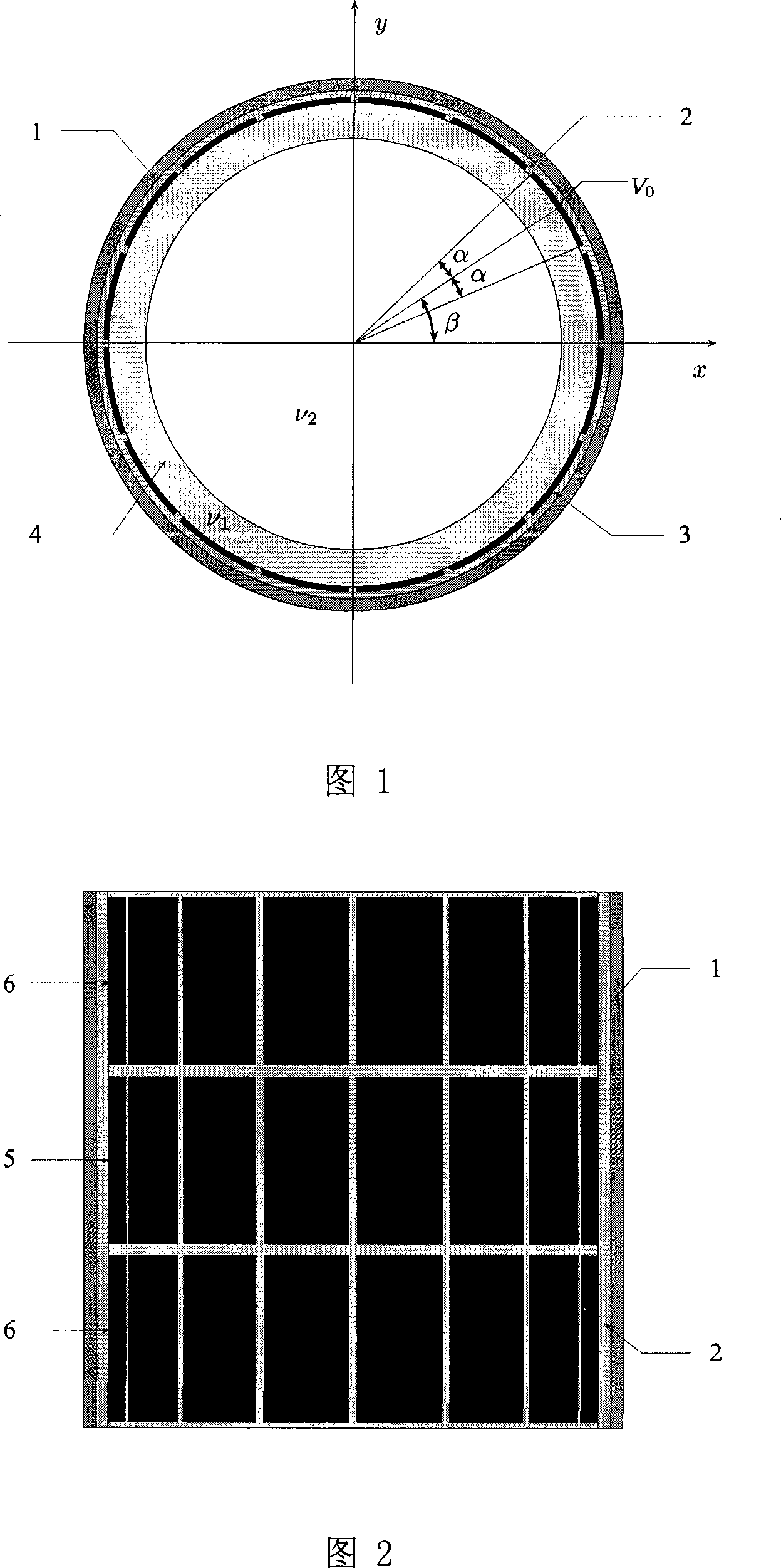
[0025] As shown in Figures 1 and 2, the sensor is installed in the measurement area. The radial cross-sectional structure of the sensor is composed of four layers, which are metal tube layer 1, insulating material layer 2, electrode array layer 3 and Insulation ring layer 4. The metal tube layer 1 plays a shielding role, and its thickness can be adjusted to meet the requirements of structural strength. The insulating material layer 2 is used to isolate the metal tube layer 1 and the electrode array layer 3; the electrode array layer 3 attached to the insulating ring layer 4 is composed of A plurality of electrodes for synchronous measurement of the real part and the imaginary part of the electrical impedance are formed; the electrodes are evenly distributed on the same c...


PUM


Abstract

The present invention provides a non-contact impedance sensor which is mounted on measuring region, the radial section structure of the sensor comprises of four layers, metal tube layer, insulation material layer, electrode array layer and insulation ring layer from outside to inside in turn. At least two electrodes are distributed in one circle on the insulation ring layer whose thickness is less than 1% of external diameter, and electric field intensity between electrode array and metal tube layer is less than breakdown strength of insulation layer. The electrode array is separated with measuring region by insulation ring layer. Two image reconstruction algorithms to realize electrical impedance tomography based on the said sensor are also provided. The present invention provides analytical medel, corresponding sensitivity distribution expression and two rapid imaging methods, the sensor can measuring synchronous same-positional dual-mode impedance, advance mutual fusion of real parts and imaginary part information of impedance distribution, predigest the design and implement of software and hardware of dual-mode measuring system.

Description

technical field [0001] The invention relates to a detection device and its application, in particular to a non-contact electrical impedance sensor and an image reconstruction method based on the sensor. Background technique [0002] Electrical Impedance Tomography (EIT) is a parameter detection technology developed in recent years for the visualization of multiphase flow and human biological tissues. In order to realize visual measurement, the core component of the whole system is the impedance sensor, which obtains the impedance information of the medium on the pipe section, and then realizes parameter detection in the form of tomography. [0003] In common industrial systems, EIT usually manifests as a single electrical resistance tomography (ERT) mode or electrical capacitance tomography (ECT) mode, and a single resistance or capacitance mode is independent of each other. And the measurement range is limited, so the acquisition of dual-mode impedance information can broa...

Claims


Application Information

Patent Timeline
Patent Type & Authority Applications(China)
IPC IPC(8): G01N27/04A61B5/053
Inventor 王化祥曹章
Owner TIANJIN UNIV
Why Eureka
Try Eureka