
Making method for dual lead device clamp

A technology for equipment wire clips and manufacturing methods, which is applied in the manufacturing of contacts, circuit/collector parts, multi-core cable end parts, etc., can solve problems such as power interruption, manufacturing inconvenience, manufacturing troubles, etc. , The effect of saving manufacturing cost and good structural strength

Inactive Publication Date: 2008-08-13
高裕彬
View PDF0 Cites 6 Cited by
  • Summary
  • Abstract
  • Description
  • Claims
  • Application Information

AI Technical Summary

Problems solved by technology

[0003] 1. The quality of the double-conductor equipment clamp molded by foundry casting is very unstable, and it is easy to produce pores during casting, so the defect rate is high, and the structural strength may be poor. After it is combined with the cable, it will withstand the wind force at high altitude for a long time Invasion, the torque caused by wind shaking will be applied to the clamp of the equipment, causing its whole body to be easily damaged and damaged. In severe cases, it will cause power interruption, and the power industry will suffer huge damage
[0004] 2. In addition to drilling the middle lock plate 20 of the equipment clamp, there is also an angle difference between the middle lock plate 20 and the body. The middle lock plate 20 and the body may be configured at 90 degrees, or at other inclination angles. Configuration, or the size of the forming area of ​​the middle lock plate 20 is different, therefore, there will be many kinds of equipment clamps with different specifications to meet the use requirements. It is necessary to prepare molds of each specification. The supply demand of multiple molds will inevitably cause great troubles in manufacturing, and greatly increase the production cost. It is very inconvenient to manufacture, and the control of production supply is not easy. It may be necessary to prepare a large amount of inventory in advance, resulting in backlog of funds

Method used


Image

  • Making method for dual lead device clamp
  • Making method for dual lead device clamp
  • Making method for dual lead device clamp

Examples


Embodiment Construction

[0026] The features and advantages of the present invention are described in detail below in conjunction with the accompanying drawings:

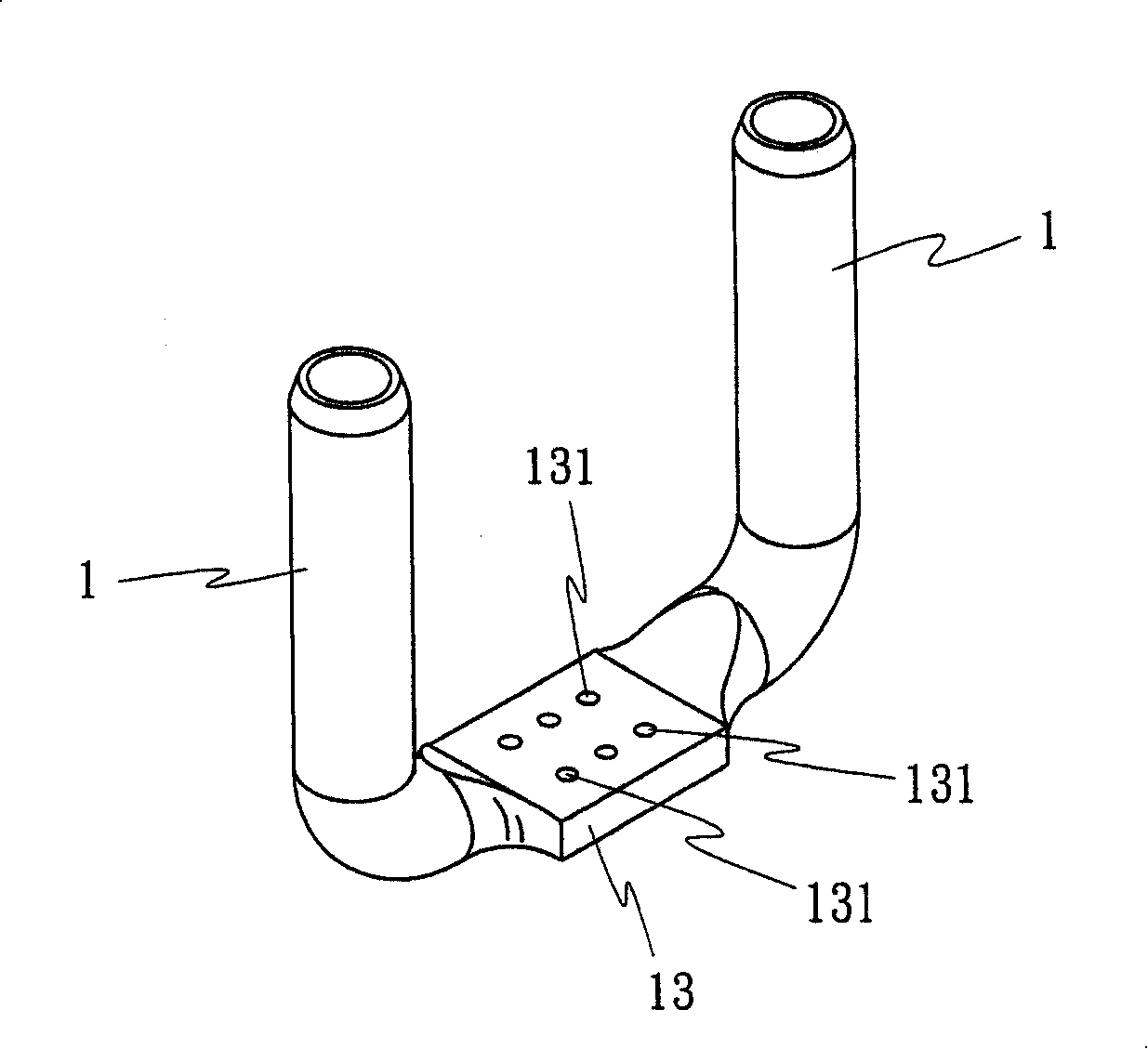
[0027] As shown in the accompanying drawings, the manufacturing method of the forged double-conductor equipment clamp provided by the present invention mainly uses two aluminum tubes 1 to pass through: bending, forging, welding, drilling and other implementation steps, so that the two aluminum tubes The tube is thus combined into an equipment clamp (eg figure 1 shown), where:

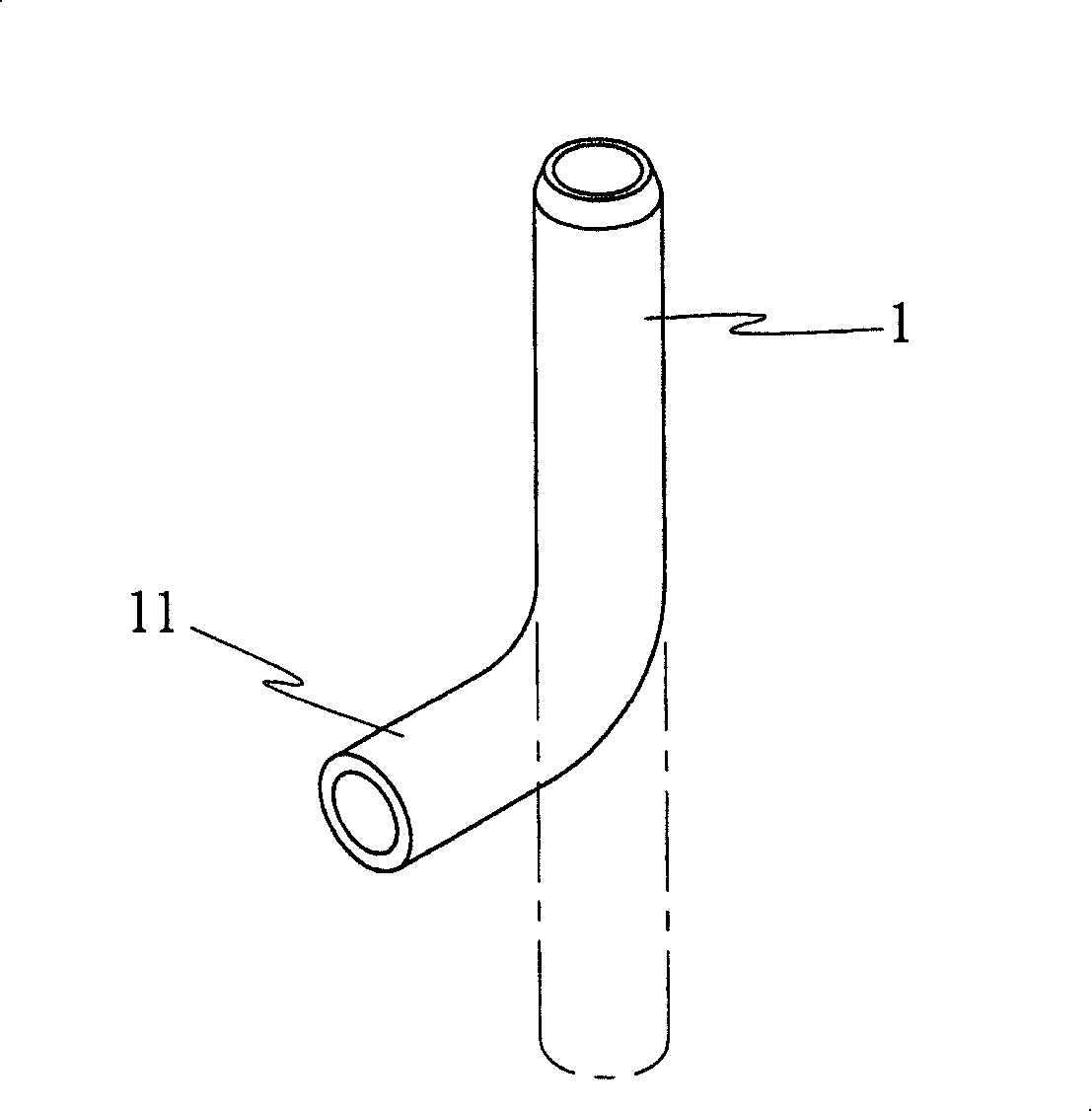
[0028] Pipe bending implementation steps: such as figure 2 As shown, the aluminum tube 1 tail 11 is processed and bent to about ninety degrees;

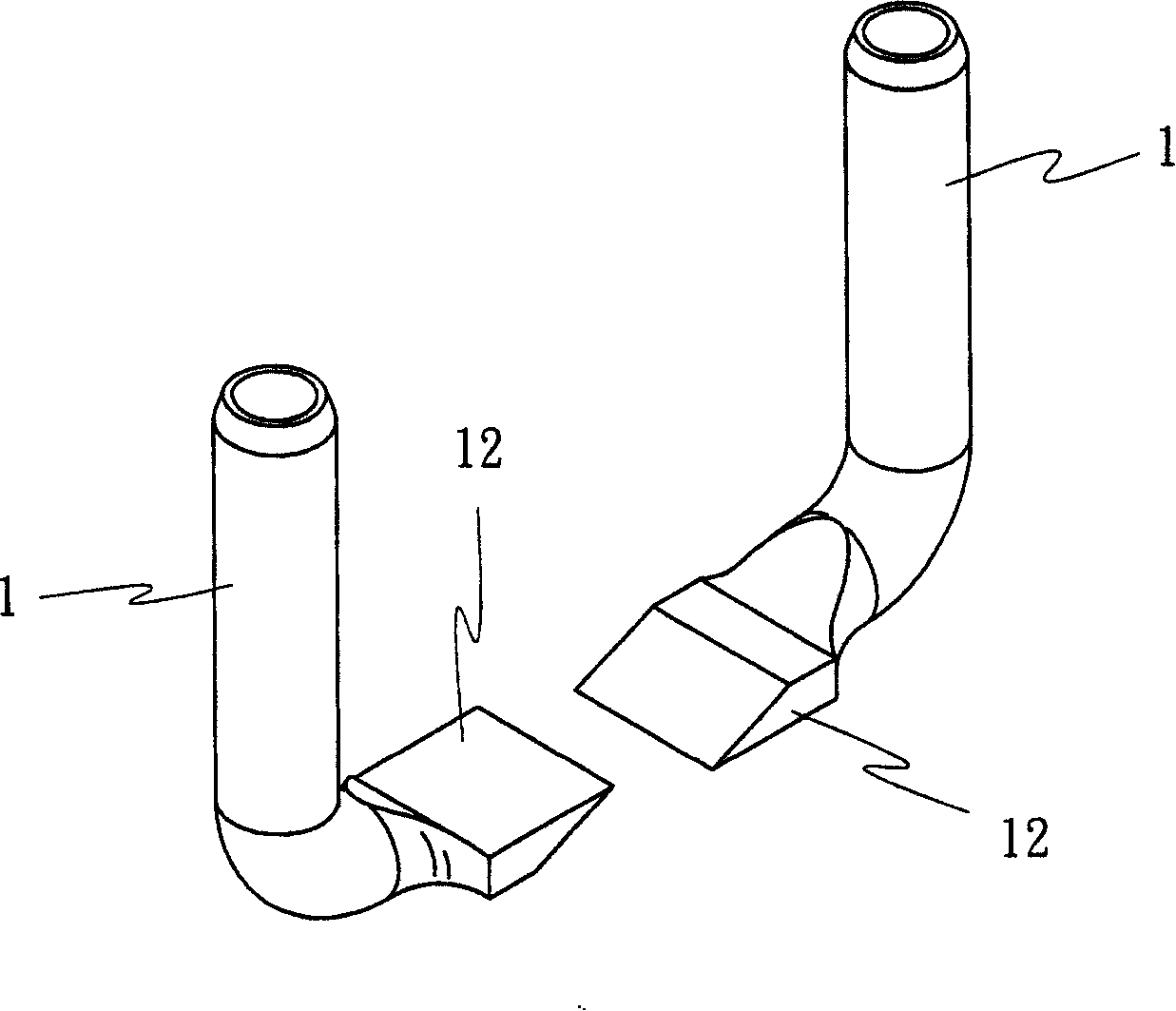
[0029] Forging implementation steps: such as image 3 As shown, the tail of the bent aluminum tube 1 is processed and forged, so that the tail 11 of the aluminum tube can form a relatively matching block-shaped part to be welded 12. During the forging process, the predetermined configuration angle of the part to be wel...


PUM


Abstract

The present invention discloses a method for manufacturing a double-conductor equipment cable clamp, in the method for manufacturing the double-conductor equipment cable clamp two aluminum pipes are combined to an equipment pipe clamp through the procedures of pipe bending, smithing, soldering, hole drilling and the like, wherein, in the cable bending actualizing procedure: the tail of the aluminum pipe is processed and bent; in the smithing actualizing procedure: the bent aluminum pipe tail is executed with processing and smithing, and the tail of the aluminum pipe can form a block part which is matched comparatively and is to be soldered; in the soldering actualizing procedure: the parts of two aluminum pipes to be soldered is executed with relative soldering combination to compose an intermediate lock plate; in the hole drilling actualizing procedure: the intermediate lock plate is perforated to compose plural holes; after the actualizing procedures of pipe bending, smithing, soldering, hole drilling and the like a pair of double-conductor equipment cable clamp can be quickly and easily manufactured to provide the connecting and combination of the cable yarn. Through the manufacturing method of the invention the equipment cable clamp can be facilitated to possess the advantages of excellent quality, good structure strength, simple production, saving manufacturing cost and the like.

Description

technical field [0001] The invention relates to a method for manufacturing a wire clip of a double-conductor device. Background technique [0002] Existing two-conductor equipment clamps for two cable joining combinations, such as Figure 11 As shown, it is generally manufactured in one piece by sand casting, so the curved pipes 10 on both sides and the locking plate 20 in the middle are made in one piece, and the drilling 201 of the locking plate 20 is processed after forming. A kind of existing two-wire equipment clamp has the following defects: [0003] 1. The quality of the double-conductor equipment clamp molded by foundry casting is very unstable, and it is easy to produce pores during casting, so the defect rate is high, and the structural strength may be poor. After it is combined with the cable, it will withstand the wind force at high altitude for a long time Invasion, the torque caused by wind shaking will be applied to the clamp of the equipment, causing its who...

Claims


Application Information

Patent Timeline
IPC IPC(8): H01R43/00H01R43/16H01R11/11
Inventor 高裕彬
Owner 高裕彬
Learn More