

LCD instilling device and method thereof
A technology of liquid crystal drops and liquid crystals, applied in nonlinear optics, instruments, optics, etc., can solve problems such as low manufacturing efficiency, low work efficiency, and long time, and achieve the effects of improving productivity, facilitating management, and saving costs
- Summary
- Abstract
- Description
- Claims
- Application Information
AI Technical Summary
Problems solved by technology
Method used
Image

Examples
Embodiment Construction
[0049] It is easy to understand that the liquid crystal instillation device and the infusion method thereof of the present invention have multiple implementation modes. The following specific embodiments and drawings are only used to illustrate the technical solution of the present invention, and should not be regarded as the entirety of the present invention or as a limitation or limitation on the technical solution of the present invention.
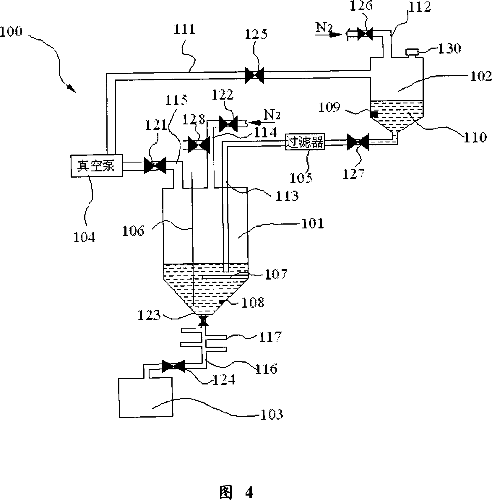
[0050] Fig. 4 is a schematic structural view of the liquid crystal instillation device of the present invention. As shown in FIG. 4 , the liquid crystal instillation device 100 of the present invention mainly includes a liquid crystal storage container 101 , a liquid crystal supply container 102 and a waste liquid recovery container 103 .
[0051] As shown in FIG. 4 , the liquid crystal storage container 101 is a container with an inverted tapered bottom structure. The resistance value measuring instrument 106 is inserted into the liqu...
PUM
 Abstract
Description
Claims
Application Information