Millimeter wave radio frequency micro electro-mechanical system dual-frequency phase shifter with trough type coplanar waveguide structure

A micro-electromechanical system and coplanar waveguide technology, applied in waveguide devices, circuits, electrical components, etc., can solve problems such as high insertion loss, large excitation voltage, and complex structure, and achieve reduced overall size, clear organization, and easy processing The effect of simple process

Inactive Publication Date: 2008-08-20
HARBIN INST OF TECH
View PDF0 Cites 10 Cited by
  • Summary
  • Abstract
  • Description
  • Claims
  • Application Information

AI Technical Summary

Problems solved by technology

[0004] In order to solve the shortcomings of existing traditional phase shifters such as high power consumption, high insertion loss, poor reliability, and high cost, the present invention also solves the problems of large excitation voltage, complex structure, and difficult To control the problem of resonance point, a millimeter-wave RF MEMS dual-frequency phase shifter with grooved coplanar waveguide structure is proposed

Method used


Image

  • Millimeter wave radio frequency micro electro-mechanical system dual-frequency phase shifter with trough type coplanar waveguide structure
  • Millimeter wave radio frequency micro electro-mechanical system dual-frequency phase shifter with trough type coplanar waveguide structure
  • Millimeter wave radio frequency micro electro-mechanical system dual-frequency phase shifter with trough type coplanar waveguide structure

Examples


specific Embodiment approach 1

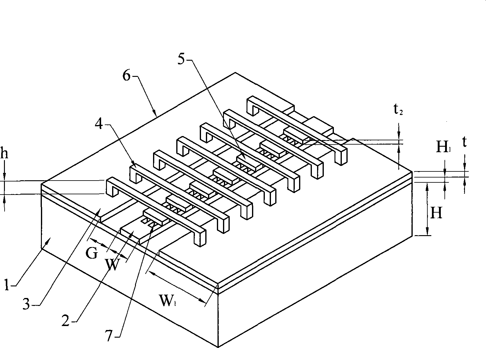
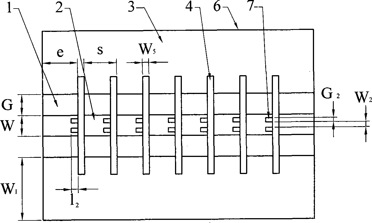
[0008] Specific implementation mode one: combine Figure 1 ~ Figure 4 This embodiment is described. This embodiment is composed of n metal bridges 4, n insulating dielectric substrates 5, and a coplanar waveguide 6. The coplanar waveguide 6 includes a substrate 1, a signal line 2, and two ground lines 3. The signal line 2 is fixed in the middle of the upper surface of the substrate 1, and the ground wire 3 is fixed at intervals on both sides of the signal line 2. The metal bridge 4 spans the substrate 1 of the coplanar waveguide 6, and the two adjacent metal bridges 4 The distance between them is S, the metal bridge 4 is perpendicular to the signal line 2, the two ends of each metal bridge 4 are respectively fixed on the two ground wires 3 on the coplanar waveguide 6, and the dielectric substrate 5 is fixed on On the upper surface of the signal line 2 below the metal bridge 4, the width of the dielectric substrate 5 is the same as that of the signal line 2, and the signal line...

specific Embodiment approach 2

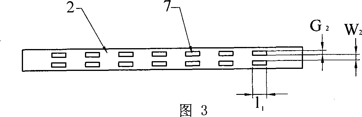
[0009] Specific implementation mode two: combination Figure 1 ~ Figure 4 Describe this embodiment, the difference between this embodiment and the specific embodiment is the length l of the rectangular groove 7 1 20~50μm, width G 2 5 to 30 μm. Other compositions and connection methods are the same as those in Embodiment 1.

specific Embodiment approach 3

[0010] Specific implementation mode three: combination Figure 1 ~ Figure 4 Describe this embodiment, the difference between this embodiment and the specific embodiment is that each group of grooves leaks out the length l of the dielectric substrate 5 2 20 to 30 μm. Other compositions and connection methods are the same as those in Embodiment 1.


PUM

PropertyMeasurementUnit
Lengthaaaaaaaaaa
Widthaaaaaaaaaa
Lengthaaaaaaaaaa

Abstract

The present invention provides a millimeter wave radio frequency micro-electro-mechanical system double-frequency phase shifter with groove type coplanar waveguide cavity bandstop which relates to double-frequency phase shifter. The present invention avoids disadvantage of high power, high insertion power, bad reliability and high cost of traditional shifter, resolves problems of high excitation voltage, complex structure and difficult to control syntony points resisted in the same device in present. The medium substrate of present invention has the same width of signal line which has n groups groove upright to surface on portrait direction, each group of groove is correspondingly set on lower part of medium substrate and is shown at least l2 length, each group of groove comprises of two rectangle grooves arranged in parallel in landscape orientation, the distance of two rectangle grooves is W2, the length of each rectangle groove is l1, the width is G2. The present invention has simple structure, clear consecution, rigor logic, relatively ideal simulation results, simple machining technics, low cost, and can be work stably in two frequencies.

Description

technical field [0001] The invention relates to a dual-frequency phase shifter. Background technique [0002] With the continuous development of science and technology, the electronic components required by various communication systems are developing rapidly in the direction of short, small, light, thin, high reliability, high speed, multi-band, and multi-polarization. In terms of performance, there is an urgent need for high-performance antennas and devices that can work at multiple frequency points at the same time, have good electromagnetic compatibility, are not susceptible to electronic interference, have small radar cross section (RCS), and have stealth / anti-stealth characteristics. The phase shifter is the most important part of the core components of radars and antennas. The operating frequency band and insertion loss of the phase shifter directly affect the anti-interference ability and sensitivity of these devices, as well as the weight, volume and cost of the sys...

Claims


Application Information

Patent Timeline
IPC IPC(8): H01P1/18
Inventor 吴群唐恺杨国辉贺训军傅佳辉孟繁义
Owner HARBIN INST OF TECH
Why Eureka
Try Eureka