Cooking fume purifier

A technology for oil fume purification and oil fume, which is applied in chemical instruments and methods, separation of dispersed particles, separation methods, etc., can solve problems such as unfavorable environmental protection, limitation of the suction port of the range hood, and inability to set the oil fume suction port, so as to achieve good suction ability and overcome The effect of noise defects

Inactive Publication Date: 2008-08-27
王君
View PDF0 Cites 18 Cited by
  • Summary
  • Abstract
  • Description
  • Claims
  • Application Information

AI Technical Summary

Problems solved by technology

Although the technical means of instantaneously removing oil fume gas can work before or during expansion, greatly improving the efficiency of oil fume exhaust, however, the generation of oil fume is around the cooktop, and the range hood installed at the rear of the cooktop has no effect on the front. The cooking fume capture ability is poor, especially the operation of the cooking operator is not static, so that the escape capture efficiency of the front fume is lower than that of the upper range hood
In addition, the installation location of this range hood is restricted (for example, it is not suitable to install in an open kitchen) and the direct discharge of oil fume is an unresolved problem
[0007] The above technical solution has the following disadvantages: the fan pushes the fume air to be discharged outward through the pipe, and the smoke exhaust effect of the range hood is affected by the limitation of the pipe and air pressure; The range hood adopts a straight discharge method, which is not conducive to environmental protection, and the work efficiency is low; and the roaring noise when the range hood is working has a serious impact on the user and the kitchen environment

Method used


Image

  • Cooking fume purifier
  • Cooking fume purifier
  • Cooking fume purifier

Examples


Embodiment 1

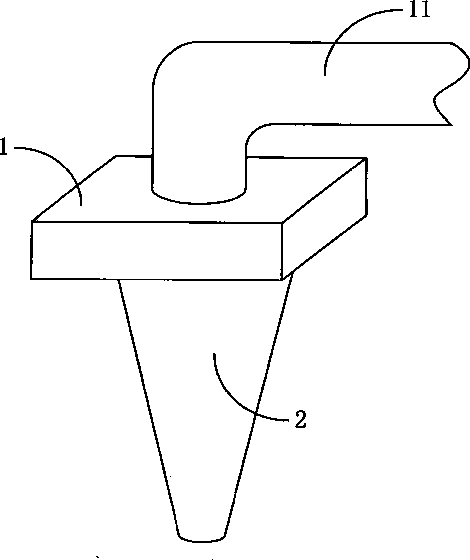
[0051] Such as image 3 As shown, this embodiment includes a fan 1 for exhausting gas through an exhaust pipe 11 . It also includes a conical cyclone pipe 2 , and the end of the cyclone pipe 2 with a larger diameter is connected to the air inlet of the fan 1 . The cyclone pipe 2 is provided with a purification component for purifying the oil fume gas flowing therethrough.

[0052] Figure 4 Shown is the internal structure of the cyclone tube 2 in this embodiment. In the figure, the purification component is a convex strip 21 spirally arranged on the inner surface of the cyclone pipe 2 . The convex strips 21 are arranged in a spiral manner.

[0053] The conical cyclone pipe 2 is a reducing pipe. When the power of the fan is constant, the air flow at both ends of the variable-diameter exhaust pipe is equal. Therefore, the end of the variable-diameter pipe with a smaller diameter generates a stronger negative pressure, thereby forming a stronger negative pressure area on the...

Embodiment 2

[0059] Such as Figure 8 As shown, the difference between this embodiment and the first embodiment above is that the end of the cyclone tube 2 with a larger diameter is connected to the air inlet of the fan 1 through a separate pipe 12 .

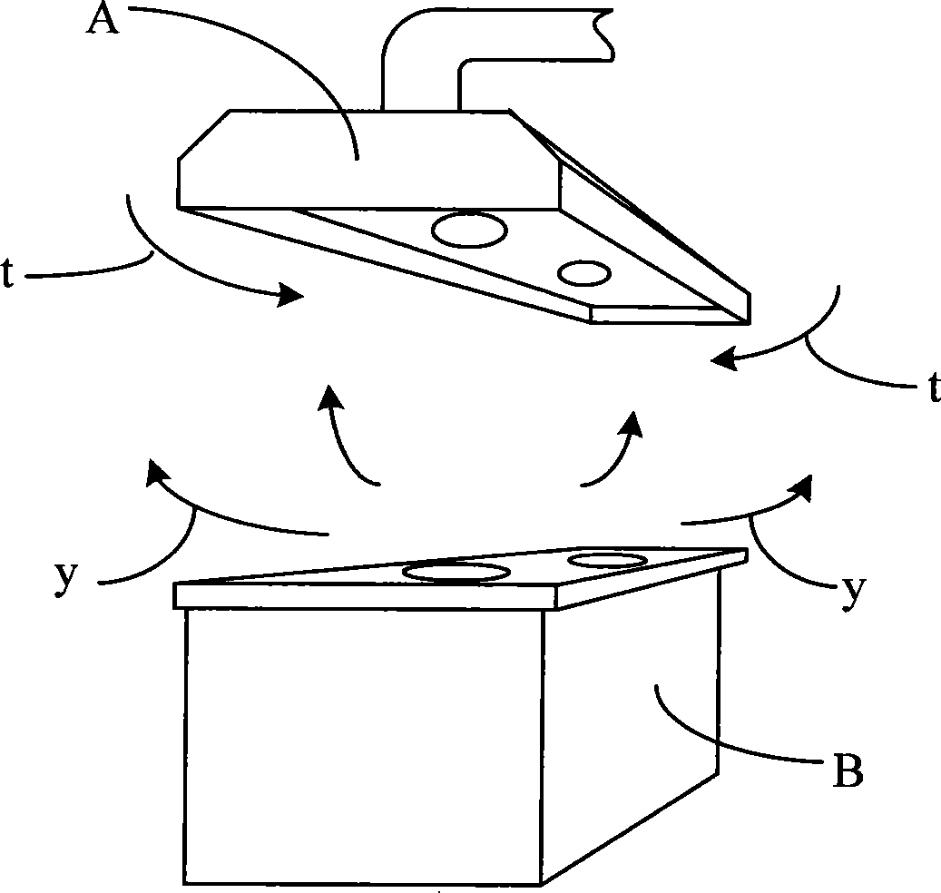
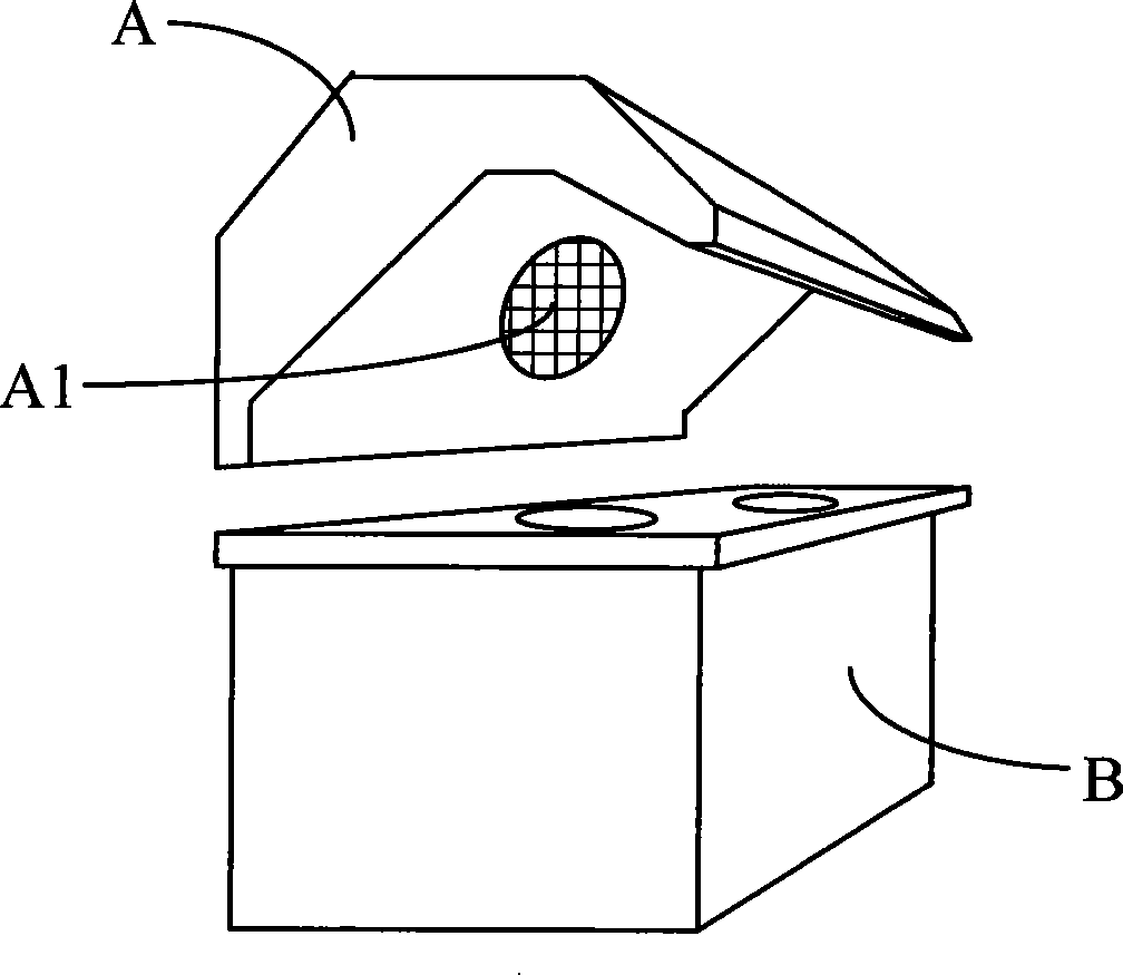
[0060] The cyclone pipe 2 and the fan 1 can be separated by the pipe 12 to form a split-type oil fume purification device. During installation, the blower fan 1 can be installed outdoors, and the cyclone pipe 2 can be installed at the stove top indoors, thereby forming a silent smoke exhaust, which overcomes the noise defect existing in the traditional range hood. In addition, in this embodiment, the end of the whirlwind pipe 2 with a smaller diameter is also connected with an oil fume suction part for capturing oil fume gas. The oil fume suction part is a cylindrical box body 3, and the surface of the box body 3 is distributed with A plurality of suction holes 31 .

[0061] The box body 3 can form a large negative pressure area in the sur...

Embodiment 3

[0068] Such as Figure 12 As shown, the difference between this embodiment and the above-mentioned two embodiments is that: a straight tube 5 is also connected to the larger end of the cyclone tube 2, and a fan impeller 4 is arranged in the straight tube 5, and on the fan impeller 4 surface A plurality of guide vanes 41 are arranged in a row.

[0069] The end with a larger diameter of the cyclone pipe 2 is the outlet of the oil fume gas, and the fan impeller 4 is arranged at the outlet to forcibly promote the rotation of the oil fume gas or enhance the rotation effect of the oil fume gas.

[0070] In order to further increase the rotational speed of the soot gas, this embodiment can also be as follows Figure 13 As shown, the fan wheel 4 is provided with a motor 42 for driving the fan wheel 4 to rotate. The fan impeller 4 installed with the motor 42 can not only provide and enhance the power of rotation, but also accelerate the flow of soot gas.

[0071] Considering the impac...


PUM


Abstract

The invention relates to an oil fume purification device, including a fan which exhausts the gas to the outside and a conical cyclone tube, one end with larger diameter of the cyclone tube is connected with an air inlet of the fan; the interior of the cyclone tube is provided with a spiral fluctuation structure which guides the air to rotator and a purification part which carries out the purification treatment of the passing oil fume. The oil fume purification device separates the oil fume granules in the oil fume which is sucked in the cyclone tube by the cyclone structure and the purification treatment structure so as to ensure that the exhaust gas contains no environmental pollution oil fume; at the same time, a pipeline is adopted to arrange the cyclone pipe and the fan separately, thus, when a kitchen exhausts the oil fume, the oil fume purification device is capable of rapidly and quietly removing the oil fume without noise.

Description

technical field [0001] The invention relates to an oil fume purification device, in particular to an oil fume purification device which utilizes the principle of cyclone centrifugation to purify sucked oil fume gas. Background technique [0002] For many years, range hoods of various structures have been widely used in people's daily life as a kind of kitchen equipment. To a certain extent, the environmental pollution caused by oil fumes in the kitchen has been removed for people, but there are still some technical defects in the existing range hoods, which mainly include not effectively purifying the oil fumes sucked into the range hoods, so that The exhausted oil fume will cause certain pollution to the surrounding environment, and then there will be very loud working noise during work. [0003] Existing range hoods, no matter they adopt the top suction mode or the side suction mode, because of their structural characteristics, all adopt the non-environmental-friendly ran...

Claims


Application Information

Patent Timeline
Patent Type & Authority Applications(China)
IPC IPC(8): B01D45/16
Inventor 王君
Owner 王君
Why Eureka
Try Eureka