
Hydrofoil craft having hydroplane function

A technology for hydrofoils and planing boats, which is applied in the construction of ships, hulls, and ships, can solve the problems of dangerous drivers, high cost, and inability to provide sufficient lift, and achieve high anti-turbulence ability and low energy consumption.

Inactive Publication Date: 2008-08-27
周洪斌
View PDF0 Cites 11 Cited by
  • Summary
  • Abstract
  • Description
  • Claims
  • Application Information

AI Technical Summary

Problems solved by technology

Its defect has: 1, the higher the speed of the planing boat, the higher its bow, the more dangerous the driver
2. The wave-making resistance is large, and the large waves will have an impact on the channel
3. There are restrictions on the length, breadth and draft of the ship, so it can only be used as a small boat and not as a big ship.
4. I am afraid of wind and waves, and may capsize in big waves
5. High fuel consumption
Its defects are as follows: 1. Once an accident occurs to the hydrofoil deeply immersed in the water, such as when water plants, fishing nets and other sundries are hung on the hydrofoil, it is easy to cause the hydrofoil to fail and cannot provide enough lift to make the hull fall and contact the water surface. The frictional resistance and wave-making resistance on the hull suddenly increase, causing the hull to stall rapidly, and its acceleration is greater than that of a car's sudden brake, which is quite dangerous
2. The hydrofoil remains in the water all the time, and the contact area with the water remains unchanged. When the speed of the ship is stable, the lift provided by the hydrofoil can only be changed by changing its angle of attack. The load is constantly changing. In order to maintain the stability of the ship while driving, the existing deep-immersed hydrofoil boats adjust the angle of attack of the hydrofoils in real time through the automatic balance control system, and change the lift provided by the hydrofoils to maintain the stability of the ship. The stability of the ship, the automatic balance control system is similar to the balance system used on the aircraft, developed by the Boeing Company of the United States, so the cost of this ship type is expensive, generally only used for military

Method used


Image

  • Hydrofoil craft having hydroplane function
  • Hydrofoil craft having hydroplane function
  • Hydrofoil craft having hydroplane function

Examples


Embodiment Construction

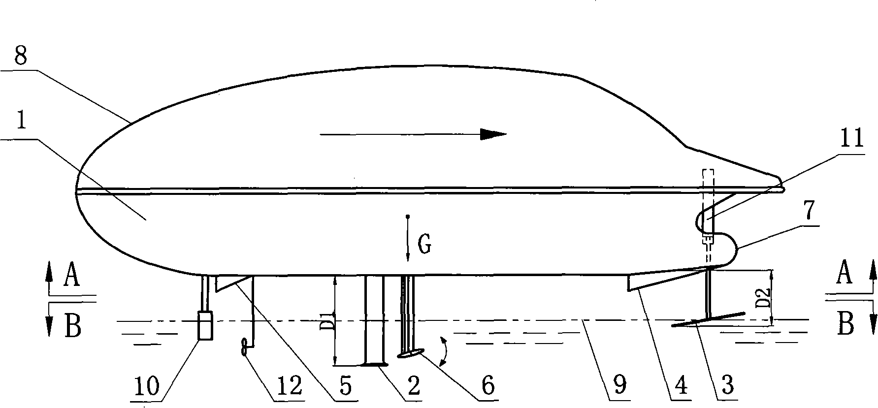
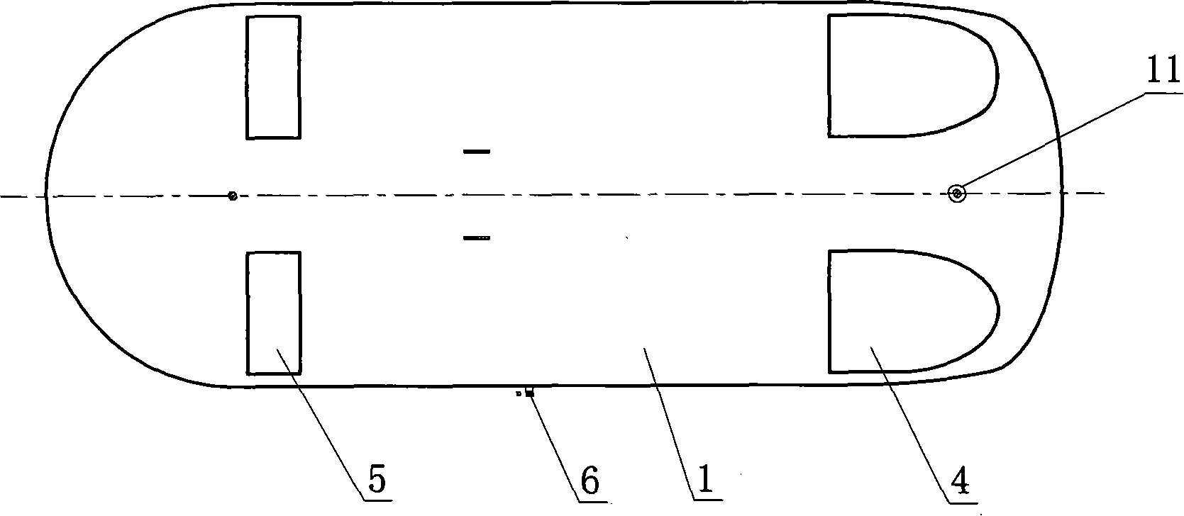
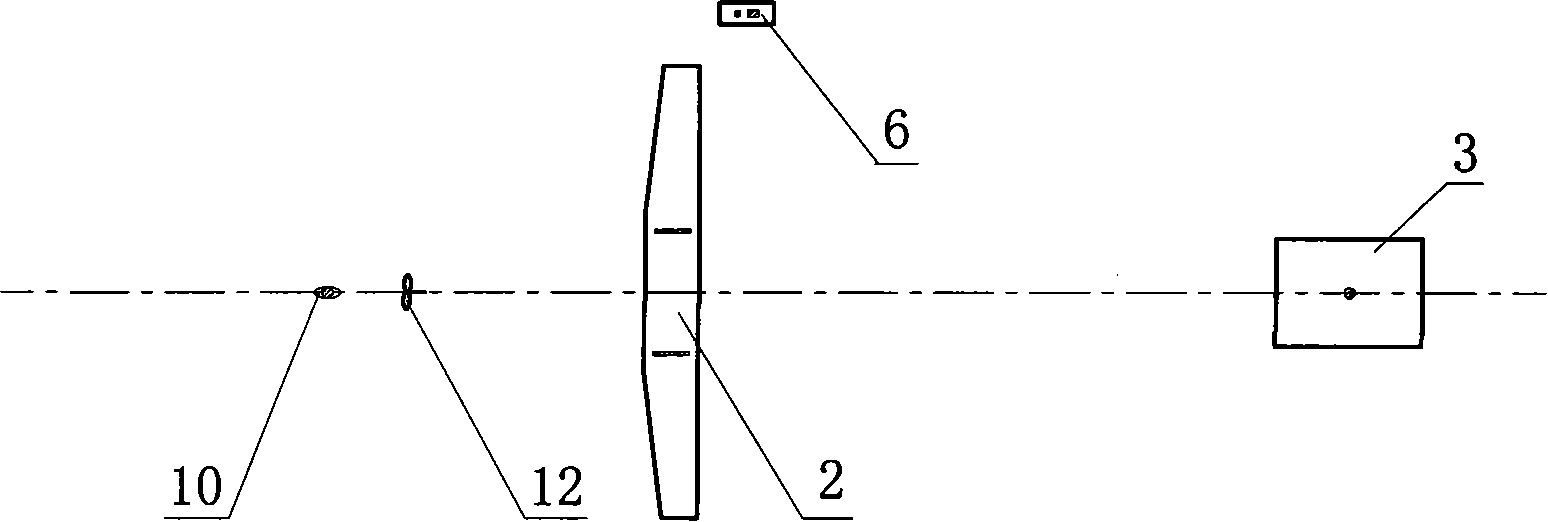
[0030] Such as Figure 1 to Figure 4 As shown, the hydrofoil boat with planing boat function of the present invention comprises a main hull 1, a propulsion device 12 and a stern rudder 10, the propulsion device 12 of the present embodiment is a propeller propulsion device, and the propulsion device 12 and the stern rudder 10 are installed At the stern of the main hull 1. The bottom of the main hull 1 is provided with a deep-immersed hydrofoil 2 and a movable hydrofoil 3 that can be used for lifting adjustment. The deep-immersed hydrofoil 2 is welded and fixed at a position close to the center of gravity G of the main hull 1 through two connecting plates, and is located at At the rear of the center of gravity G, the movable hydrofoil 3 is arranged at the bow of the main hull 1, the distance D1 from the deep-immersed hydrofoil 2 to the main hull 1 is greater than the distance D2 from the movable hydrofoil 3 to the main hull 1, and the movable hydrofoil 3 The lifting adjustment ...


PUM


Abstract

The invention discloses a hydrofoil ship with a displacement boat function, which comprises a main hull, a propulsion device and a stern rudder, wherein a deep-wetted hydrofoil and a movable sliding hydrofoil which can achieve lift adjustment are arranged at the bottom of the main hull, the deep-wetted hydrofoil is arranged at the rear portion of the gravity of the main hull while the movable sliding hydrofoil is arranged on the head portion of the main hull, and the distance between the deep-wetted hydrofoil and the main hull is longer than that between the movable sliding hydrofoil and the main hull. The hydrofoil ship has the advantages of fast route speed, sound dynamic stability, high safety, energy-saving and low production cost.

Description

technical field [0001] The invention relates to the field of shipbuilding, in particular to a hydrofoil boat with the function of a planing boat. Background technique [0002] Among existing ships and boats, similar to the present invention with planing boat and hydrofoil craft. [0003] The manufacturing cost of the planing boat is relatively low. When it is running at high speed, the bow of the boat rises, and about one-third of the tail is immersed in the water. The boat is supported by the relative momentum between the bottom and the water surface. The frictional resistance between the water and the hull is reduced, so a higher speed can be achieved. Its defective has: 1, the higher the speed of the planing boat, the higher the bow, and the more dangerous the driver. 2. The wave-making resistance is large, and the large waves will have an impact on the waterway. 3. There are restrictions on the length, breadth and draft of the ship, so it can only be used as a small b...

Claims


Application Information

Patent Timeline
IPC IPC(8): B63B1/24
Inventor 周洪斌
Owner 周洪斌
Learn More