Middle-low pressure gas collection technique

A process method and gas gathering technology, which can be used in earth-moving drilling, production of fluids, wellbore/well components, etc., can solve the problems of inconvenient production and management, and increase production costs.

Inactive Publication Date: 2008-08-27
XIAN CHANGQING TECH ENG
View PDF0 Cites 5 Cited by
  • Summary
  • Abstract
  • Description
  • Claims
  • Application Information

AI Technical Summary

Problems solved by technology

When the number of wells in the gas field is large, the well spacing is small, and the output of a single well is low, the ab

Method used


Image

  • Middle-low pressure gas collection technique
  • Middle-low pressure gas collection technique
  • Middle-low pressure gas collection technique

Examples


Embodiment Construction

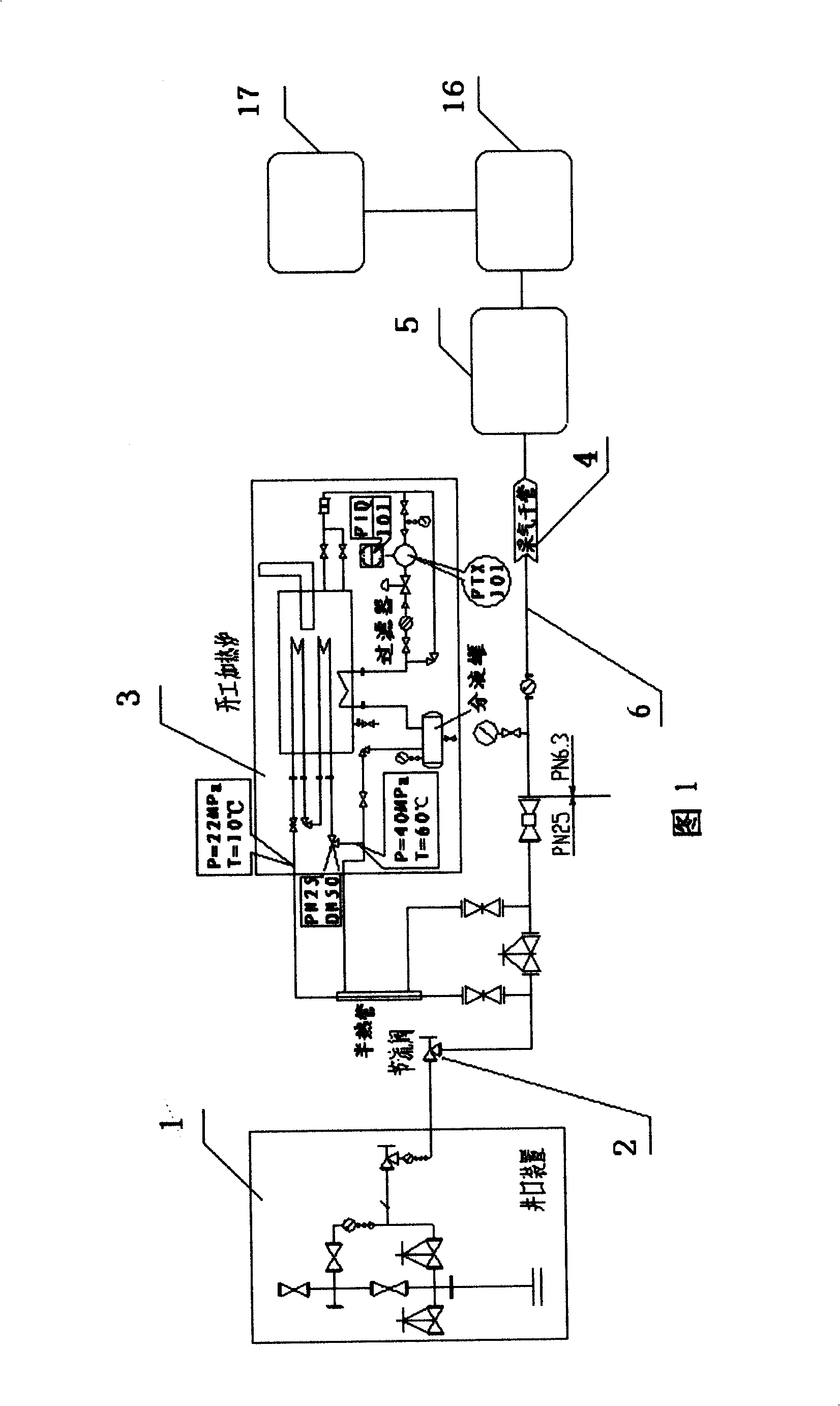
[0016] As shown in Figure 1, it is a conventional gas field treatment process. The natural gas in the gas well is connected to the wellhead device 1 through a pipeline, and the natural gas output directly from the well has a high pressure. It must pass through the throttle valve 2 and then be connected to the heating furnace 3 , so that the natural gas pressure becomes lower. In this process, the control system is required to adjust various valves, and the flow, temperature, and pressure need to be measured. Then it is connected to the gas gathering station 5 through the gas production pipeline 4 for processing, and at the same time, the wellhead needs to inject hydrate inhibitors to prevent the pipeline from freezing or to insulate the pipeline. When the number of wells in the gas field is large, the well spacing is small, and the output of a single well is low, the above-mentioned process obviously brings a lot of inconvenience to production and management, and increases the ...


PUM


Abstract

The invention relates to a gas transmission device for a gas field, in particular to a method for a middle and low pressure gas collecting process, comprising a gas well, a wellhead device (1), a gas transmission pipeline, a gas collecting station (5) and a central processing plant. The invention is characterized in that the pressure of a wellhead is reduced to a middle pressure or a low pressure through an underground throttleer (12), is directly subject to a gas-liquid separation and a gas supercharging through a gas collecting pipeline (4) being connected to the gas collecting station (5), and is transmitted to a central processing mechanism (17) for deoiling and dewatering through a gas collecting branch trunk (16). The method for the middle and low pressure gas collecting process achieves aims of reducing blockage probability of hydrate in a pitshaft, increasing the property of liquid carrying, reducing the operating pressure of the pipeline and protecting a reservoir through underground throttling.

Description

technical field [0001] The invention relates to a gas field gas transmission device, in particular to a medium and low pressure gas gathering process. Background technique [0002] As shown in Figure 1, in the conventional gas field treatment process, due to the high pressure of the natural gas directly output from the well, in order to safely transport the natural gas to the gas gathering station 5 for gas-liquid separation, the natural gas is transported through the gas gathering branch line 6 Go to the central treatment plant 7 for deoiling and dehydration. [0003] After the natural gas in the well is connected to the wellhead device 1 through the pipeline, it needs to pass through the throttle valve 2 and then connect to the heating furnace 3, and the gas pressure at the wellhead will be reduced through the throttle valve 2 and the heating furnace 3. Then it is transported to the gas gathering station 5 through the main gas production pipe 4 for processing, and at the ...

Claims


Application Information

Patent Timeline
IPC IPC(8): E21B43/00E21B33/03E21B43/34
Inventor 刘祎何宗平王登海杨光刘子兵薛岗
Owner XIAN CHANGQING TECH ENG
Why Eureka
Try Eureka