Photon crystal wave-guide polarization beam splitter

A photonic crystal waveguide and polarization beam splitter technology, which is applied in the coupling of optical waveguides, polarization elements, optics, etc., can solve the problem that the polarization beam splitter structure cannot be compatible with devices

Inactive Publication Date: 2008-08-27
SHANGHAI INST OF TECHNICAL PHYSICS - CHINESE ACAD OF SCI
View PDF0 Cites 30 Cited by
  • Summary
  • Abstract
  • Description
  • Claims
  • Application Information

AI Technical Summary

Problems solved by technology

[0003] The purpose of the present invention is to provide a photonic crystal waveguide polarization beam splitter, which solves the problem that

Method used


Image

  • Photon crystal wave-guide polarization beam splitter
  • Photon crystal wave-guide polarization beam splitter
  • Photon crystal wave-guide polarization beam splitter

Examples


Embodiment Construction

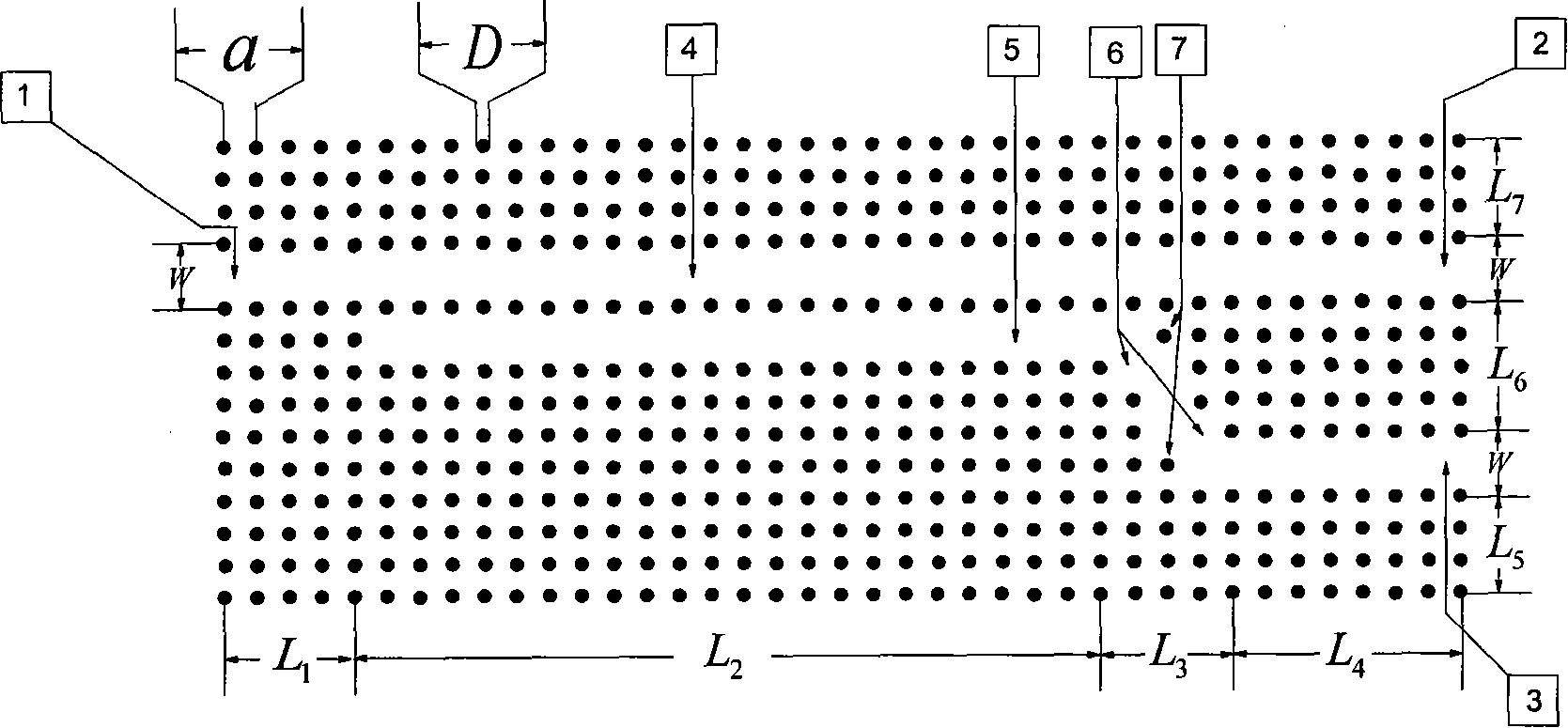
[0043] According to the technical solution of the present invention, we take the polarizing beam splitter whose working wavelength is λ=5.13 μm as an example, combined with the attached figure 1 To illustrate the implementation method of the device.

[0044] The main structural parameters of the device are designed as follows:

[0045] Lattice constant of the device (distance between two cylindrical dielectric pillars): a=0.3894×λ=2um.

[0046] Diameter of the dielectric cylinder: D=0.4×a=0.8um.

[0047] The width of the waveguide (the distance between the two rows of dielectric cylinders above and below the waveguide): W=2×a=4um.

[0048] The length from the entrance port 1 to the edge of the coupling area: L 1 ≥3a In the embodiment, take L 1 =4*a=8um.

[0049] Coupling zone length: L 2 =23×a=46um.

[0050] Transition length from coupling region to uncoupling region: L 3 =4*a=8um. (Note, a dielectric column is deleted at the convex right angle 6 of the waveguide at t...


PUM


Abstract

The invention discloses a photonic crystal waveguide polarizing beam splitter which introduces a line defect to form a structure of a coupled waveguide in a two-dimensional tellurium dielectric rod photonic crystal, and implements beam splitting for TE beam and TM beam by using different coupled lengths of waveguides of the TE beam and the TM beam. The characteristics of the implementation of the polarizing beam splitter by adopting a two-dimensional photonic crystal waveguide are as follows: firstly, compared with the prior various polarizing beam splitter devices, the polarizing beam splitter adopting the two-dimensional photonic crystal waveguide can implement a polarizing beam splitting with high degree of polarization and high extinction ratio; secondly, the device can be provided with a smaller size, and can be structurally compatible with the prior photonic crystal device to meet a requirement of integration ratio; thirdly, the polarizing beam splitter adopting the two-dimensional photonic crystal waveguide has a very flexible structure, and can implement the polarizing beam splitting of any wavelength in a range from 3.5 to 35mu m for wavelengths through adjusting a length of a coupling region or a lattice constant. The invention also discloses a designing idea and a particular structural design of the polarizing beam splitter, an optical performance, etc. of the polarizing beam splitter acquired from the designing idea.

Description

technical field [0001] The invention relates to an optical element, in particular to a polarization beam splitter applied in a waveguide based on a photonic crystal structure. Background technique [0002] A photonic crystal is a microstructure in which periodic dielectric constant modulation is artificially introduced by various methods, and the period of the dielectric constant can be compared with the wavelength of light. The periodic change of the dielectric function can modulate the state mode of photons in the material, so that the photonic band gap appears. When the frequency of light is within the range of the photonic band gap, it will not be able to propagate in any direction in the photonic crystal. Photonic crystals have important application prospects. Due to its characteristics, it is possible to fabricate new principles or high-performance devices that could not be fabricated before. At present, the theoretically and experimentally realized photonic crystal ...

Claims


Application Information

Patent Timeline
IPC IPC(8): G02B6/27G02B5/30G02B1/02
Inventor 陆卫王健陈效双李宁李志锋张波陈平平李天信甄红楼
Owner SHANGHAI INST OF TECHNICAL PHYSICS - CHINESE ACAD OF SCI
Why Eureka
Try Eureka