Linear optical modulators and method of linear optical modulation

a linear optical modulator and optical modulation technology, applied in the field of optical modulators, can solve problems such as signal fidelity reduction

Inactive Publication Date: 2007-01-09
LUMERA CORP
View PDF57 Cites 8 Cited by
  • Summary
  • Abstract
  • Description
  • Claims
  • Application Information

AI Technical Summary

Problems solved by technology

The presence of higher order harmonic signals creates distortion of the fundamental harmonic RF signal, which decreases signal fidelity.

Method used


Image

  • Linear optical modulators and method of linear optical modulation
  • Linear optical modulators and method of linear optical modulation
  • Linear optical modulators and method of linear optical modulation

Examples


examples

[0022]The following example(s) is illustrative and does not limit the Claims.

[0023]The following is a brief description of the method used to calculate spur-free dynamic range.

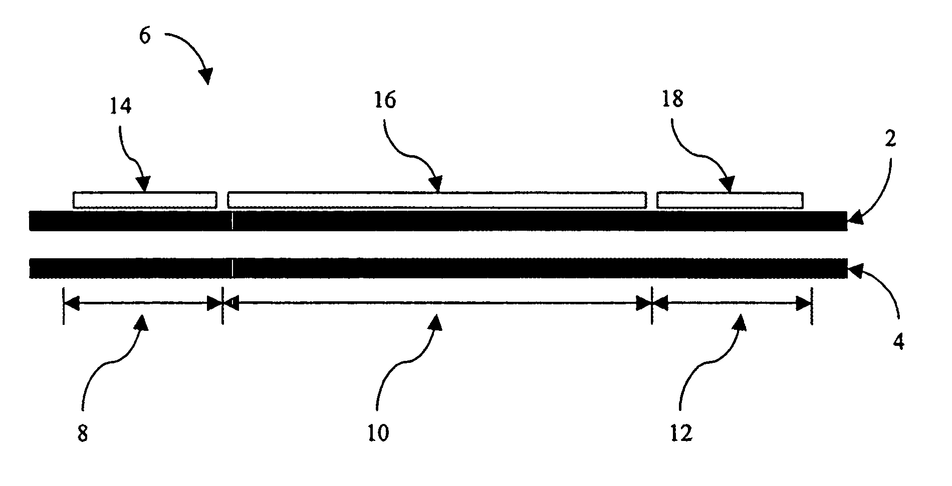
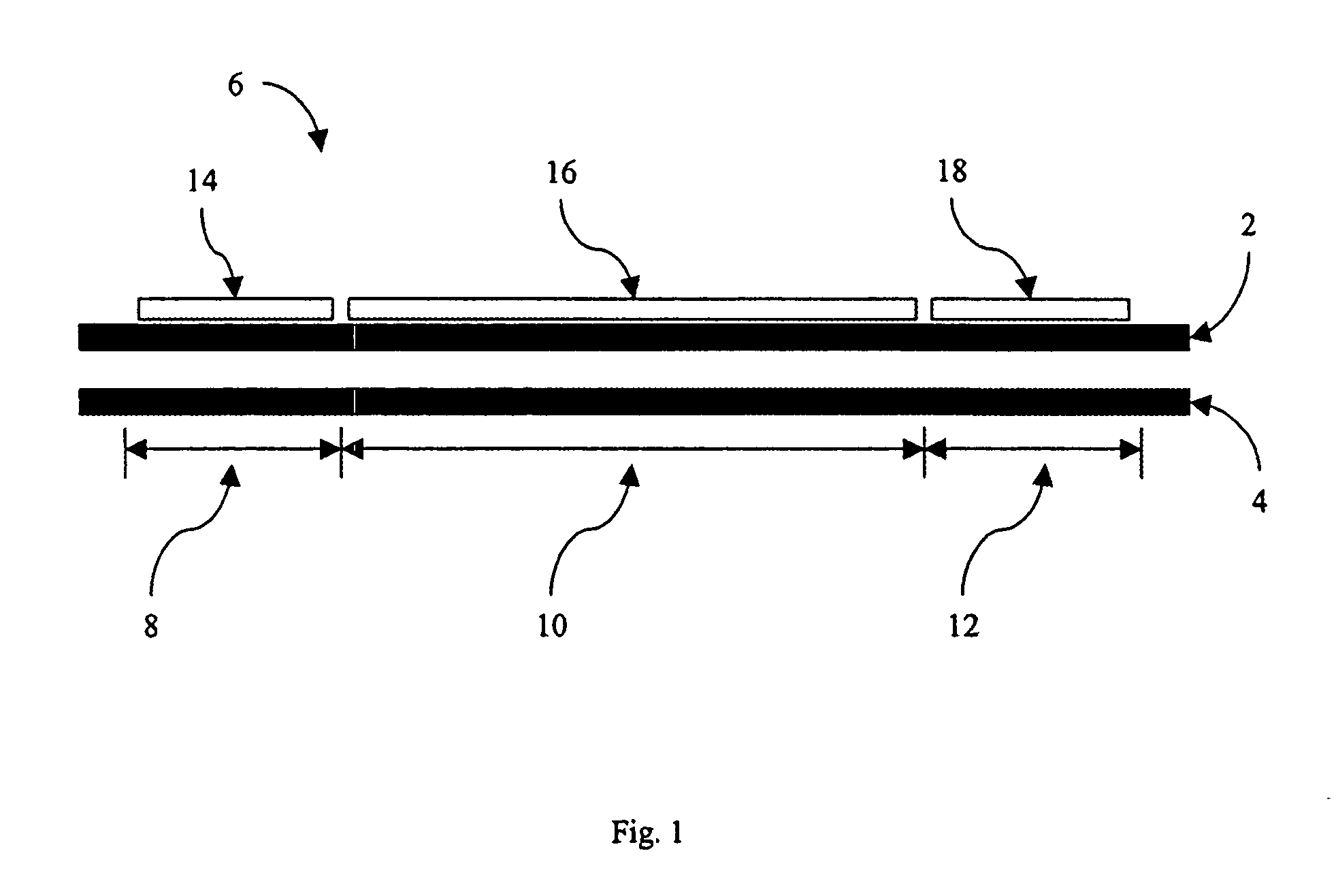
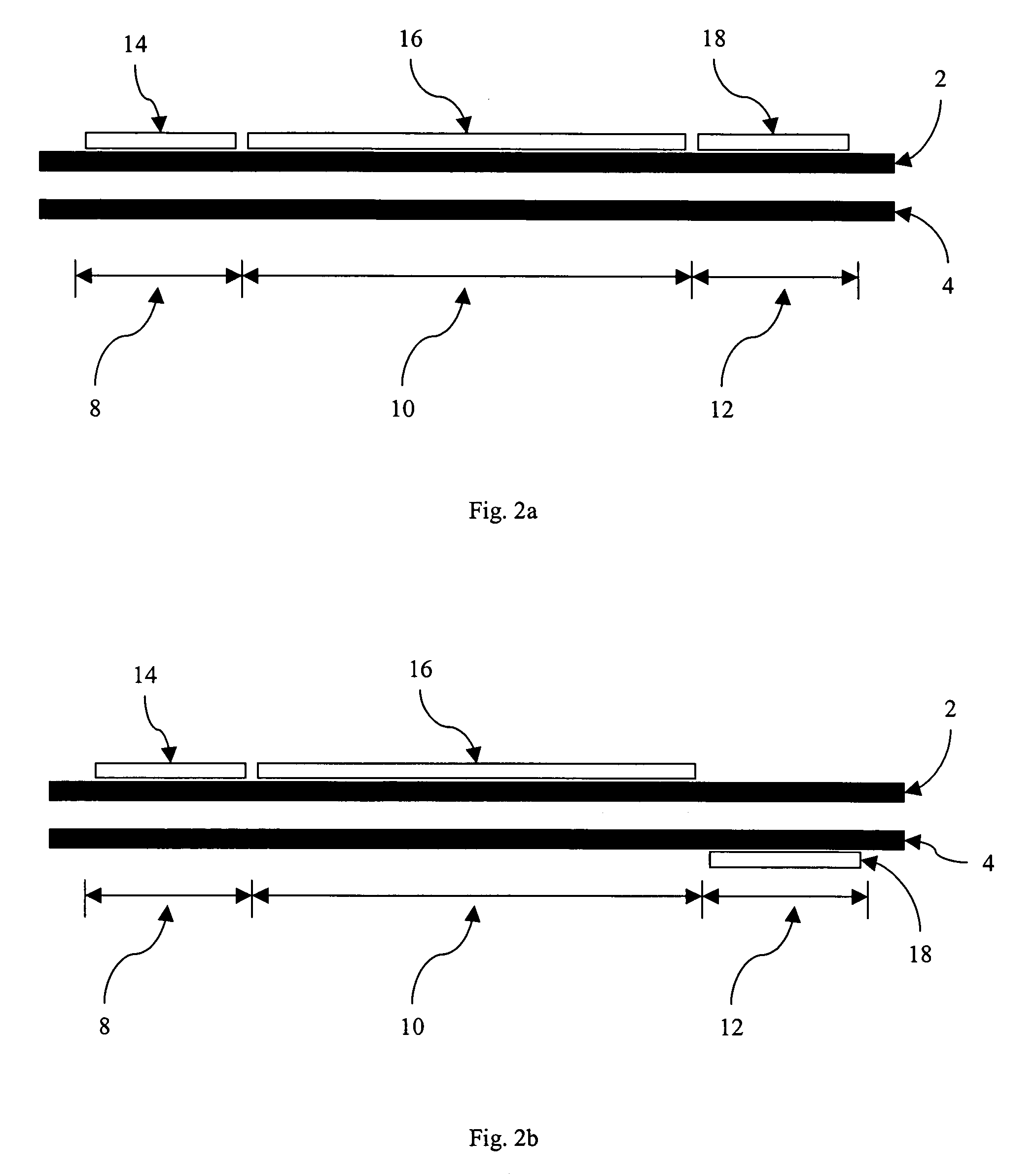
[0024]The optical modes that result from coupling electrical power (RF and DC) into the optical waveguides are calculated using methods such as that reported in Lin, et al. J. Lightwave Tech. 14(9), 2012 (1996). The optical modes for each section of the device are calculated separately. The output of first bias section is used as the input for the modulation section. The output of the modulation section is used as the input for the second bias section. The output of the second bias section is used as the input of the detector. The input of the detector is used to calculate SFDR. We assume that all noise, including the signal dependent shot noise, is additive. With this proviso, we can obtain a simple expression relating the microwave (RF) power out of the receiver Pout with the microwave power, Pin, incident o...


PUM

PropertyMeasurementUnit
thicknessaaaaaaaaaa
lengthaaaaaaaaaa
thicknessaaaaaaaaaa

Abstract

A device that comprises: a) a first optical waveguide; b) a second optical waveguide; c) an optical coupling region including the first and second optical waveguides, the optical coupling region characterized as having at least one coupling length and comprising a first bias section, a modulation section, and a second bias section arranged such that light propagates serially through the first bias section, the modulation section, and the second bias section; d) a first bias electrode for biasing the first bias section; e) a modulating electrode for applying a modulating voltage to the modulation section, the modulating electrode being positioned to control the refractive index of the first optical waveguide; and f) a second bias electrode for biasing the second bias section.

Description

BACKGROUND OF THE INVENTION[0001]This invention was made with Government support under F30602-03-C-0119 awarded by the AFRL. The Government has certain rights in this invention.[0002]All patents, patent applications, and publications cited within this application are incorporated herein by reference to the same extent as if each individual patent, patent application or publication was specifically and individually incorporated by reference.[0003]The invention relates generally to optical modulators, and more specifically to analog optical modulators. Optical modulators encode radio frequency (RF) onto an optical carrier. When an RF signal is encoded onto an optical carrier, there is a fundamental harmonic RF signal accompanied by higher order RF harmonic signals, all of which are encoded onto the optical carrier. The presence of higher order harmonic signals creates distortion of the fundamental harmonic RF signal, which decreases signal fidelity. High fidelity encoding of the RF si...

Claims


Application Information

Patent Timeline
Patent Type & Authority Patents(United States)
IPC IPC(8): G02F1/03G02F1/07
CPCG02F1/3134G02F1/065G02F1/0147G02F2203/20
Inventor BINTZ, LOUIS J.DINU, RALUCA
Owner LUMERA CORP
Why Eureka
Try Eureka