
Scanning mechanism, method of machining workpiece, and machine tool

A technology of scanning mechanism and concentrating device, applied in the field of scanning mechanism, can solve the problems of high-speed positioning or high-precision positioning difficulties, etc.

Inactive Publication Date: 2008-08-27
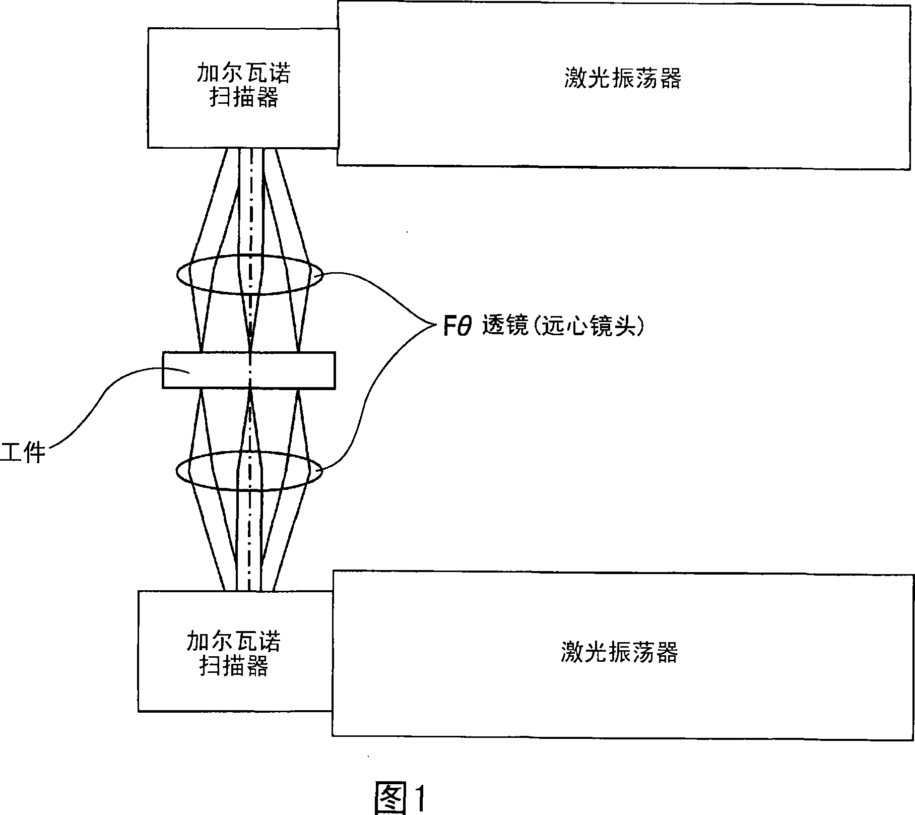
FUJITSU LTD
View PDF0 Cites 3 Cited by
  • Summary
  • Abstract
  • Description
  • Claims
  • Application Information

AI Technical Summary

Problems solved by technology

Furthermore, high-speed positioning or high-precision positioning becomes relatively difficult

Method used


Image

  • Scanning mechanism, method of machining workpiece, and machine tool
  • Scanning mechanism, method of machining workpiece, and machine tool
  • Scanning mechanism, method of machining workpiece, and machine tool

Examples


Embodiment Construction

[0042] An embodiment of the laser scanner will be described below with reference to the accompanying drawings.

[0043] FIG. 4 is a schematic diagram showing a brief structure of a laser scanner according to an embodiment of the present invention.

[0044] The laser scanner of this embodiment includes a condensing lens that condenses a laser beam emitted by a laser source (not shown), and a condensing lens holder with a focusing mechanism as light condensing means, the condensing lens A lens holder supports the condenser lens. Adjusting screws are arranged around the periphery of the condenser lens holder. These adjustment screws are screwed into the condenser lens mounting plate. Correspondingly, by rotating the condenser lens holder, the condenser lens holder can move along the Y-axis direction in the figure, that is, move along the direction indicated by the horizontal arrow in Figure 4, and the focus position of the laser beam can be moved Adjusted to lie on the surface...


PUM

PropertyMeasurementUnit
diameteraaaaaaaaaa
transmittivityaaaaaaaaaa

Abstract

A scanning mechanism that scans a scanning object with a light beam has light-collecting means for collecting the light beam that is emitted by a light source; driving means for driving the light-collecting means in a direction orthogonal to an optical axis of the light-collecting means; first reflecting means provided near a first aide of the scanning object, for reflecting the light beam collected by the light-collecting means to allow the light beam to be incident on the scanning object; and second reflecting means provided near a second side of the scanning object that is opposite to the first side of the scanning object, for reflecting the light beam collected by the light-collecting means to allow the light beats to be incident on the scanning object.

Description

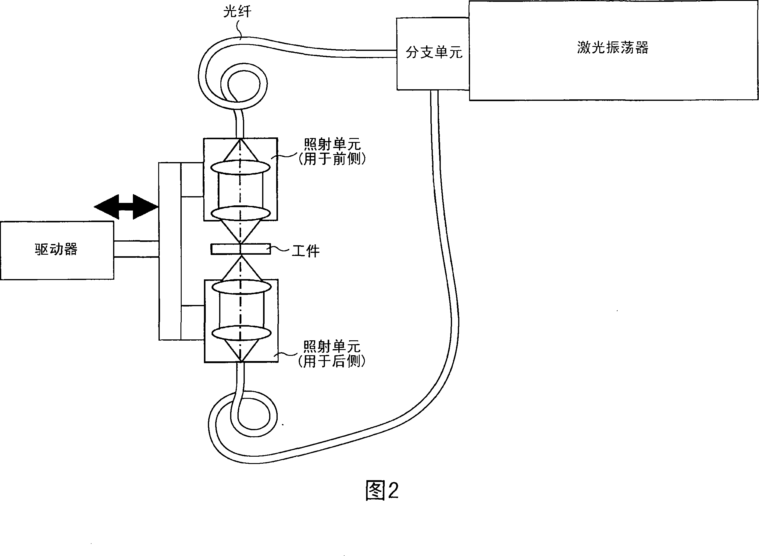
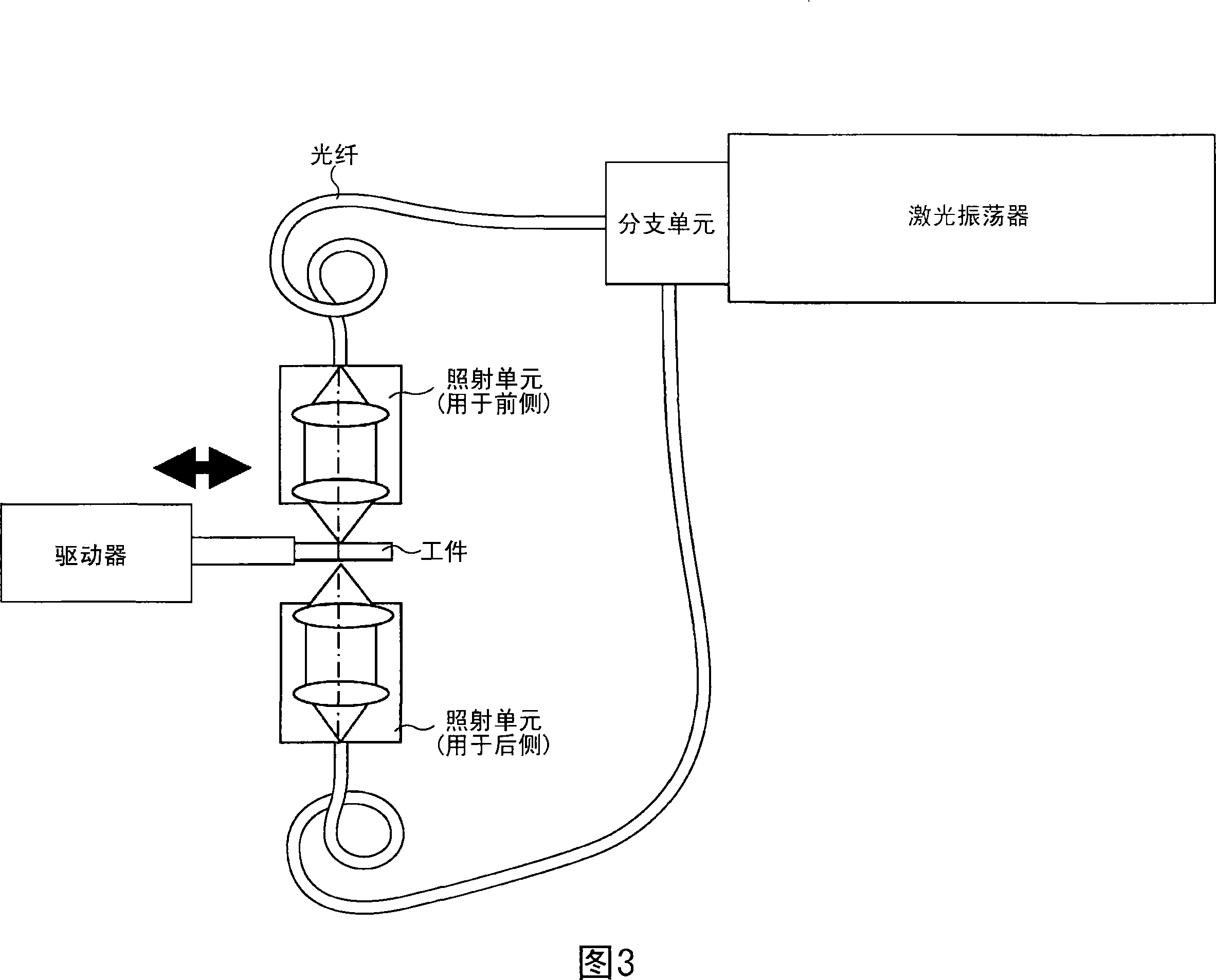
technical field [0001] The present invention relates to a scanning mechanism for performing scanning using a light beam such as a laser beam. The invention also relates to a method of machining various types of workpieces, and to a machining device. Background technique [0002] In order to process different types of workpieces, laser processing is often used. For laser processing, a laser beam is emitted to the surface of the workpiece by a laser oscillator. Modern laser processing requires that the emitted laser beam be directed by optical elements such as lenses and mirrors to scan the desired position of the workpiece. [0003] Currently, the workflow of laser processing is as follows: [0004] In the first type, a high-power laser oscillator is used and applied to high-density, high-speed welding. This type of laser processing is used, for example, in the automation industry. [0005] In the second type, a low-power laser oscillator is used and applied to micromach...

Claims


Application Information

Patent Timeline
Patent Type & Authority Applications(China)
IPC IPC(8): G02B26/10B23K26/06B23K26/03
CPCB23K26/0604B23K26/067G11B5/84B23K26/082B23K26/0619B23K26/355B23K2101/36
Inventor 松下直久古井寿一
Owner FUJITSU LTD
Learn More