Developing spray nozzle structure and method for spraying developing solution

A developer and nozzle technology, applied in the direction of electrical components, semiconductor/solid-state device manufacturing, circuits, etc., can solve the problems of poor development, incomplete development, time-consuming and cost-effective, etc.

Inactive Publication Date: 2008-08-27
AU OPTRONICS CORP
View PDF0 Cites 4 Cited by
  • Summary
  • Abstract
  • Description
  • Claims
  • Application Information

AI Technical Summary

Problems solved by technology

The design of this known developer nozzle 10 is not easy to concentrate the air bubbles 102 to be discharged smoothly from the bottom of each air vent (Air Vent) 16 of the nozzle cavity 12, but needs to wait until Figure 1B The state shown, that is, when large or a large number of air bubbles 102 have accumulated inside the nozzle cavity 12, it is possible to discharge them from the exhaust hole 16
However, once a large amount of air bubbles 102 are accumulated in the nozzle cavity 12, these air bubbles 102 are more likely to be sprayed onto the substrate 180 along with the developer 100 (such as Figure 1C shown) above; because these bubbles 102 may lead to incomplete development and affect the subsequent etching process
That is, if the nozzle 10 allows too many air bubbles 102 to be brought to the substrate 180 along with the developer 100, poor development will be caused, which will seriously affect the yield of the process, requiring subsequent rework and resulting in unnecessary time and cost
Although it is known that the developer nozzle 10 can remove air bubbles through regular machine maintenance, but because it is mostly done manually, when there are many machines that need to be maintained, it takes time and labor costs, and the process efficiency is not good.

Method used


Image

  • Developing spray nozzle structure and method for spraying developing solution
  • Developing spray nozzle structure and method for spraying developing solution
  • Developing spray nozzle structure and method for spraying developing solution

Examples


Embodiment Construction

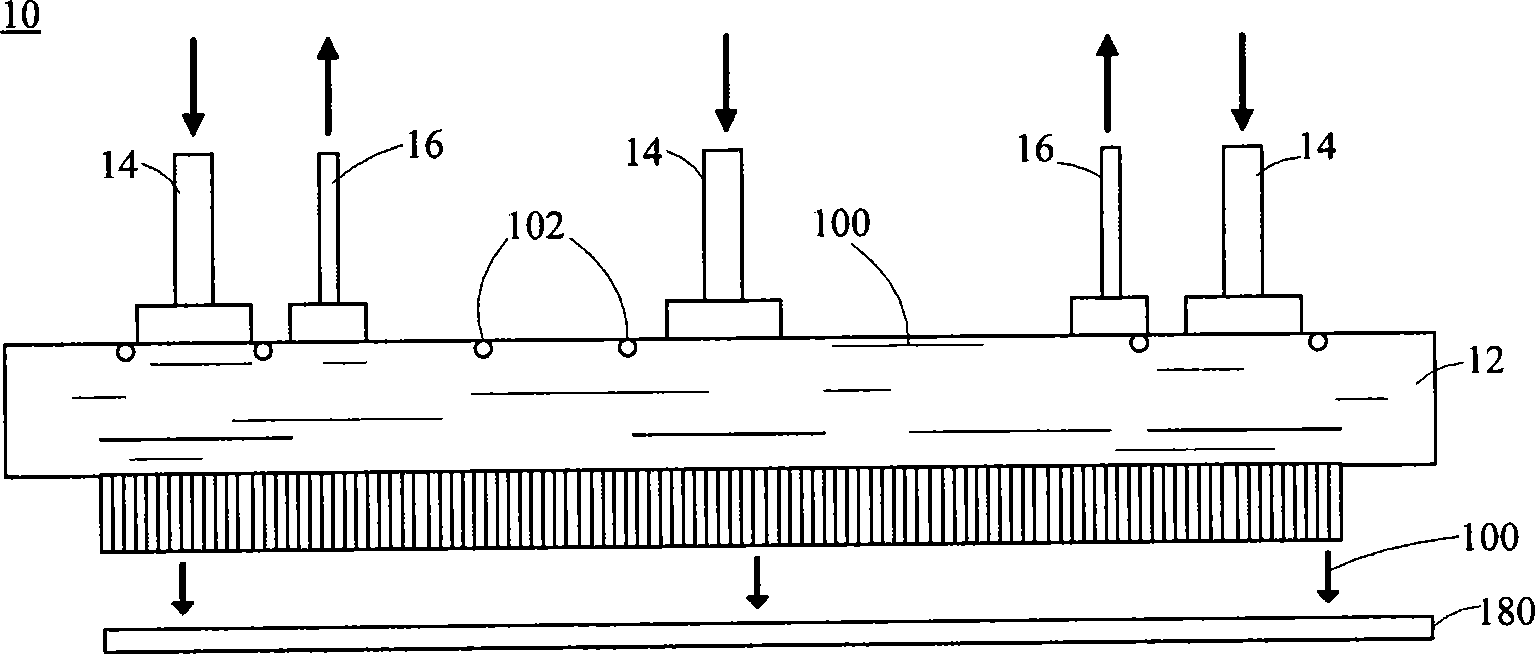
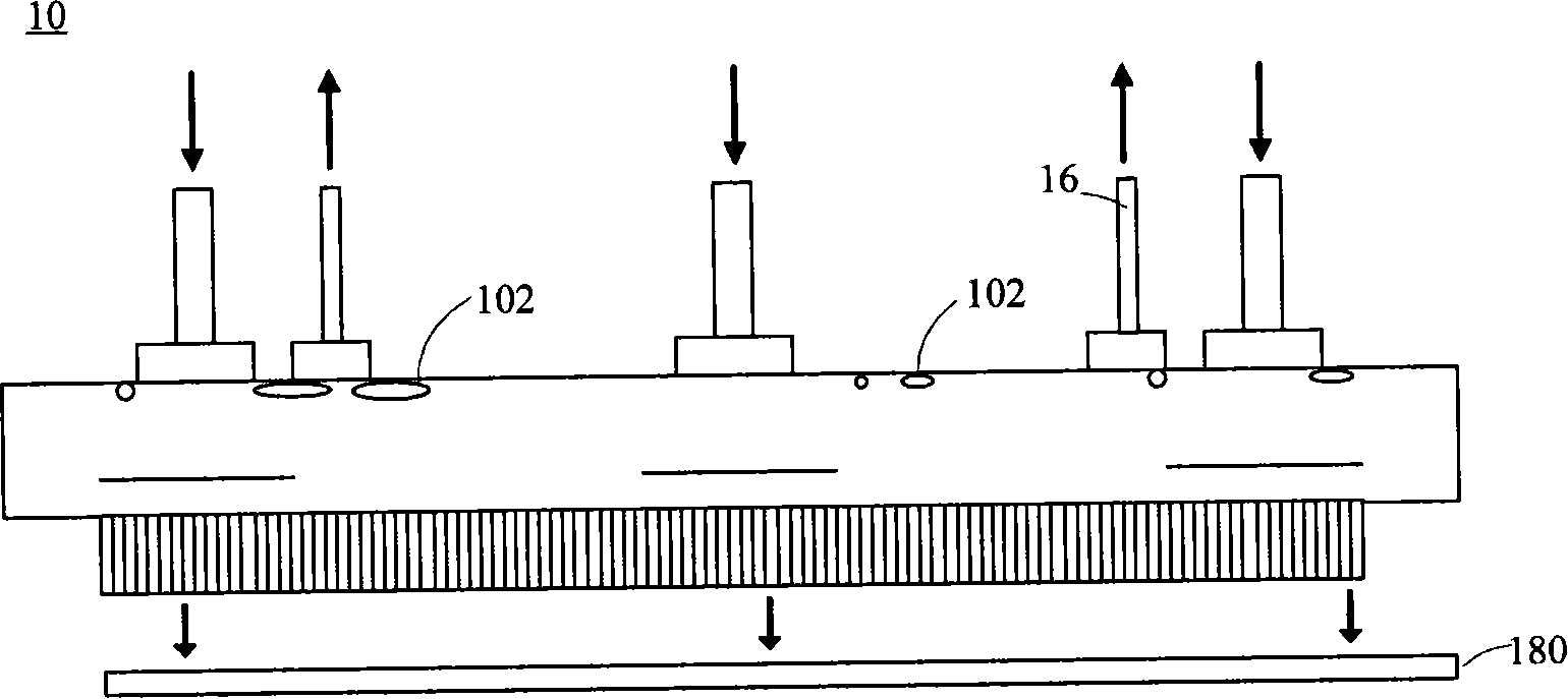
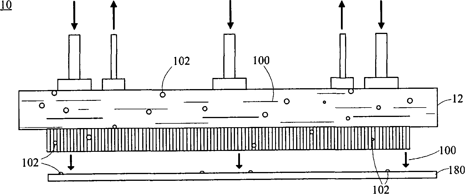
[0028] first as Figure 2A and Figure 2B As shown, it is a developing nozzle structure 20 according to a preferred embodiment of the present invention, which is suitable for a thin-film transistor liquid crystal display panel 200 to perform the developing process of the yellow light segment of the transistor array process, and the developing nozzle structure 20 mainly includes : nozzle cavity 22, several bubble discharge pipes 24, several injection pipes 26, an auxiliary injection pipe 27, several spraying pipes 28 and several gate devices 30.

[0029] The inside of the nozzle chamber 22 is divided into upper and lower parts by the several side-by-side gate devices 30, namely a first chamber 221 and a second chamber 223 below the first chamber 221. The purpose of its separation is to utilize liquid Different from the gas density, the gas floats upwards, so that the bubbles 212 generated when the developer 210 is injected will rise and concentrate in the first chamber 221 in ...


PUM


Abstract

The invention provides a developing nozzle structure and a method for spray coating developing solution. The developing nozzle structure comprises a nozzle cavity and a valve system, wherein, the nozzle cavity is provided with a first chamber, a second chamber which is positioned under the first chamber, an injection pipe which supplies the developing solution and injects the developing solution into the second chamber, and a spray coating pipe which is communicated with the second chamber and positioned under the second chamber; the valve system is arranged between the first chamber and the second chamber; when the valve system is opened, air bubbles in the developing solution enter into and concentrate in the first chamber; when the valve system is closed, the air bubbles in the first chamber are isolated from the developing solution in the second chamber, and the developing solution in the second chamber is sprayed out through the spray coating pipe. In this way, the air bubbles which are brought out to a panel along with the developing solution are greatly reduced, thereby the technological efficiency can be improved.

Description

technical field [0001] The invention relates to a developing nozzle structure and a method for spraying developing solution, in particular to a developing nozzle structure and a method for spraying developing solution used in the manufacture of semiconductor elements. Background technique [0002] Generally, an active matrix thin film transistor liquid crystal display (Active matrix thin film transistor liquid crystal display) uses a thin film transistor or similar active element (Active element) to generate an electric field to turn the liquid crystal (LC), and then control the direction of light. The manufacture of this type of thin film transistor liquid crystal display can be roughly summarized into three main manufacturing processes: the front-end transistor array (Array) manufacturing process, the middle-stage liquid crystal cell (Cell) manufacturing process, and the rear-end module assembly (Module Assembly) manufacturing process. The transistor array (Array) manufact...

Claims


Application Information

Patent Timeline
IPC IPC(8): G03F7/30H01L21/00H01L21/84
Inventor 何松勋张耿志
Owner AU OPTRONICS CORP
Why Eureka
Try Eureka